Magnetic cylinder body assembly applied to electronic mutual inductor

An electronic transformer and magnetic cylinder technology, which is applied in the direction of transformer/inductor magnetic core, inductor, transformer/inductor parts, etc., can solve the problem of poor adhesion between winding wire and magnetic cylinder body, winding wire and The winding wire is prone to problems such as movement and failure to work normally, achieving the effect of increasing the degree of fit

Pending Publication Date: 2022-03-29
苏州佳成机械制造有限公司
View PDF0 Cites 0 Cited by
  • Summary
  • Abstract
  • Description
  • Claims
  • Application Information

AI Technical Summary

Problems solved by technology

[0003] When the traditional magnetic cylinder winds the coil, the winding coil is directly wound on the outer wall of the magnetic cylinder. There is a certain gap between the winding wires and the winding wires are prone to movement, which will lead to poor adhesion between the coiled winding wires and the magnetic cylinder, which will cause it to fail to work normally. Propose a magnetic cylinder assembly for electronic transformer

Method used


Image

  • Magnetic cylinder body assembly applied to electronic mutual inductor
  • Magnetic cylinder body assembly applied to electronic mutual inductor
  • Magnetic cylinder body assembly applied to electronic mutual inductor

Examples


Embodiment Construction

[0023] The following will clearly and completely describe the technical solutions in the embodiments of the present invention with reference to the accompanying drawings in the embodiments of the present invention. Obviously, the described embodiments are only some, not all, embodiments of the present invention. Based on the embodiments of the present invention, all other embodiments obtained by persons of ordinary skill in the art without making creative efforts belong to the protection scope of the present invention.

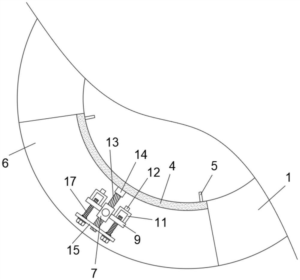
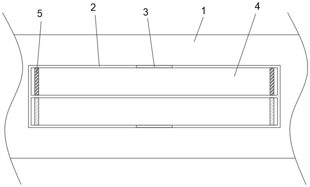
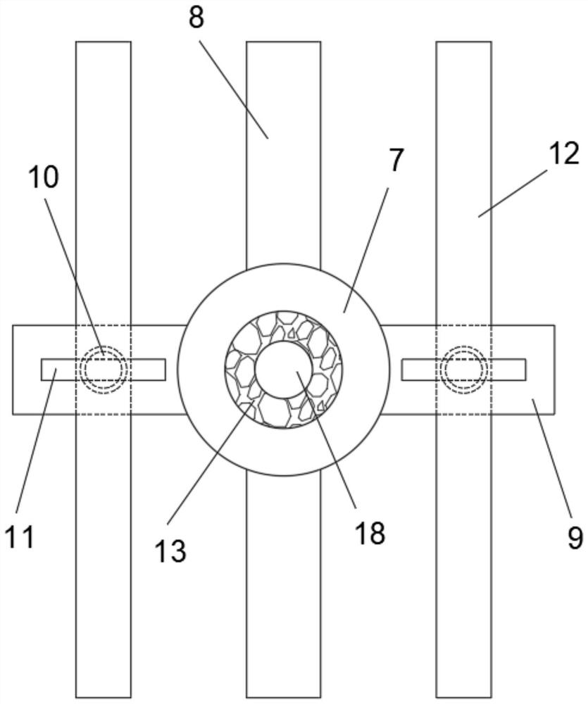
[0024] The invention provides a technical solution, a magnetic cylinder assembly applied to an electronic transformer, such as figure 1 and figure 2 As shown, including the magnetic cylinder body 1 and the tight limit column 13, the inner wall of the magnetic cylinder body 1 is excavated with an inner movable groove 2, and the top and bottom ends of the inner movable groove 2 are provided with a movable shaft 3, and the movable shafts 3 are connected to each ...


PUM


Abstract

The invention relates to the technical field of electronic mutual inductors, and discloses a magnetic cylinder assembly applied to an electronic mutual inductor, an abutting limiting sleeve is arranged in a clamping adjusting groove, and sleeve supporting columns are fixed to the top and the bottom of the abutting limiting sleeve correspondingly; first limiting side plates are fixed to the outer walls of the two sides of the abutting limiting sleeve correspondingly, the abutting limiting column is ejected out towards the side close to the arc-shaped movable top plate, and the abutting limiting column slides in the abutting limiting sleeve when driving the U-shaped abutting supporting rod to move so that stable horizontality can be kept. And after the two ends of the side, away from the abutting limiting column, of the U-shaped abutting supporting rod make contact with the side walls, close to each other, of the two arc-shaped movable top plates correspondingly, the U-shaped abutting supporting rod is ejected out of the outer portion of the inner side movable groove, and therefore the attaching degree of the winding coil and the magnetic cylinder body is increased, and the winding coil can be tightly bound to the outer portion of the magnetic cylinder body. And the problem that later-stage work is affected due to shaking is avoided.

Description

technical field [0001] The invention relates to the technical field of electronic transformers, in particular to a magnetic cylinder assembly applied to electronic transformers. Background technique [0002] The electromagnetic transformer is a kind of electronic transformer, which is used to measure the large current and high voltage flowing through the substation. With the help of the transformer, it can measure the electric energy and send signals to the protection and control system. It is composed of iron core and winding. The coil is combined, and the iron core is also called the magnetic cylinder. [0003] When the traditional magnetic cylinder winds the coil, the winding coil is directly wound on the outer wall of the magnetic cylinder. There is a certain gap between the winding wires and the winding wires are prone to movement, which will lead to poor adhesion between the coiled winding wires and the magnetic cylinder, which will cause it to fail to work normally. ...

Claims


Application Information

Patent Timeline
Patent Type & Authority Applications(China)
IPC IPC(8): H01F27/30H01F27/24H01F38/20G01R1/16
CPCH01F27/306H01F27/24H01F38/20G01R1/16
Inventor 沈建华蔡国强
Owner 苏州佳成机械制造有限公司
Why Eureka
Try Eureka