Twisting forming device and method for stator end thread end

A forming device and stator end technology, applied in forming tools, manufacturing stator/rotor bodies, manufacturing tools, etc., can solve problems such as unachievable height, quality problems, and inability to use multi-layer stator wire head twist, to ensure product quality, improve The effect of production efficiency

Pending Publication Date: 2022-04-01
成都华川电装有限责任公司
View PDF1 Cites 0 Cited by
  • Summary
  • Abstract
  • Description
  • Claims
  • Application Information

AI Technical Summary

Problems solved by technology

[0003] The applicant has previously applied for a utility model patent with the publication number CN208508747U and a mechanical device for bending stator copper wires. This mechanical device is mainly used for twisting single-layer stator wire ends, but not for multi-layer stator wire ends. In addition, the equipment uses the upper and lower curved cams to control the vertical distance during the twisting process. The height of the cam structure cannot be realized. When the length of the wire head changes, it may cause problems such as copper wires being squeezed together after forming, resulting in quality problems. question
This problem is more likely to occur especially for the twisting of the multi-layer stator end wire ends

Method used


Image

  • Twisting forming device and method for stator end thread end
  • Twisting forming device and method for stator end thread end
  • Twisting forming device and method for stator end thread end

Examples


Embodiment Construction

[0041] The present invention is further described below.

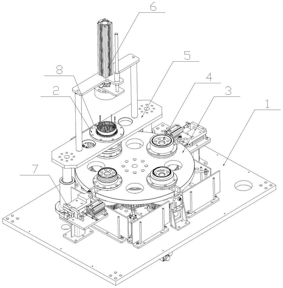
[0042] Such as Figure 2-6 As shown, the twisted forming device of the stator end wire head disclosed in the present invention includes a frame 1, a stator placement mechanism 2, a position conversion mechanism 3 and two twisting dies 4;

[0043] The position conversion mechanism 3 is arranged on the frame 1, and the twisting die 4 is arranged on the position conversion mechanism 3, and is transferred to the stator twisting station of the frame 1 by the position conversion mechanism 3 or leaves the stator twisting station. position, the twisted wire die 4 is connected with a twisted wire driving mechanism;

[0044] The stator placement mechanism 2 is arranged at the stator twisting station of the frame 1 , and the stator placement mechanism 2 is connected with an adjustment mechanism 5 for adjusting the distance between the stator placement mechanism 2 and the twisting die 4 .

[0045] The twisting forming method of th...


PUM


Abstract

The invention relates to the field of stator processing, and discloses a distortion forming device and method for a stator end thread end. The device comprises a rack, a stator placing mechanism, a position switching mechanism and two wire twisting dies, the position conversion mechanism is arranged on the rack, the wire twisting die is arranged on the position conversion mechanism and is converted to a stator wire twisting station of the rack or leaves the stator wire twisting station through the position conversion mechanism, and the wire twisting die is connected with a wire twisting driving mechanism; and the stator placing mechanism is arranged at a stator wire twisting station of the rack and is connected with an adjusting mechanism for adjusting the distance between the stator placing mechanism and the wire twisting die. According to the device, the stator placing mechanism and the wire twisting dies are separated, the different wire twisting dies are paired with the stator placing mechanism through switching of the position switching mechanism, wire twisting of each layer of end wire heads of a stator is achieved, the problem that an existing wire twisting device cannot adapt to wire twisting of stators with different wire head lengths is solved, the production efficiency is improved, and meanwhile the production cost is reduced. And the product quality can be effectively ensured.

Description

technical field [0001] The invention relates to the field of stator processing, in particular to a twist forming device and method for stator end wire ends. Background technique [0002] The stator is an important part of the motor. Under the condition of the same volume, in order to obtain higher efficiency and power, many stators use flat copper wire windings instead of round wire windings to improve the core slot fill rate. The plan of the flat wire stator, since the U-shaped hairpin wire is inserted into the iron core, such as figure 1 and figure 2 As shown, the final wiring state is obtained by twisting the hairpin head, and then subsequent welding and other processing methods are performed. Twisting wire ends at the end of the stator, because there are many wire ends, requires a high twist angle, so this process is a very critical process, which directly affects product quality. [0003] The applicant has previously applied for a utility model patent with the publi...

Claims


Application Information

Patent Timeline
Patent Type & Authority Applications(China)
IPC IPC(8): B21F7/00B21D11/10B21D11/14B21D11/22B21D37/10H02K15/02
Inventor 邵凡张小兵周林
Owner 成都华川电装有限责任公司
Why Eureka
Try Eureka