
Equipment binding method, device and system

A binding relationship and equipment technology, applied in transmission systems, electrical components, etc., can solve problems such as low fault tolerance and inability to replace a piece of equipment immediately, and achieve low-cost effects

Active Publication Date: 2022-04-01
ADVANCED NEW TECH CO LTD
View PDF11 Cites 1 Cited by
  • Summary
  • Abstract
  • Description
  • Claims
  • Application Information

AI Technical Summary

Problems solved by technology

However, this solution needs to enter the location of the device in advance, and the fault tolerance is low. Once the device has a problem, it cannot be replaced with a device of the same type immediately.

Method used


Image

  • Equipment binding method, device and system
  • Equipment binding method, device and system
  • Equipment binding method, device and system

Examples


Embodiment Construction

[0074] Embodiments of the present application provide a device binding method, device and system.

[0075] In order to enable those skilled in the art to better understand the technical solutions in the present application, the technical solutions in the embodiments of the present application will be clearly and completely described below in conjunction with the drawings in the embodiments of the present application. Obviously, the described The embodiments are only some of the embodiments of the present application, but not all of them. Based on the embodiments in this application, all other embodiments obtained by persons of ordinary skill in the art without creative efforts shall fall within the scope of protection of this application.

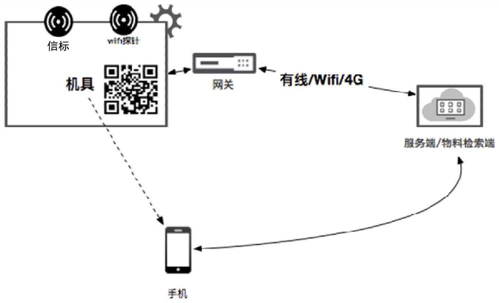
[0076] figure 1 It is a schematic diagram of a scenario of device binding in this application. Such as figure 1 As shown, the equipment on the upper left side is the equipment to be bound; the server / material retrieval terminal on the ri...


PUM


Abstract

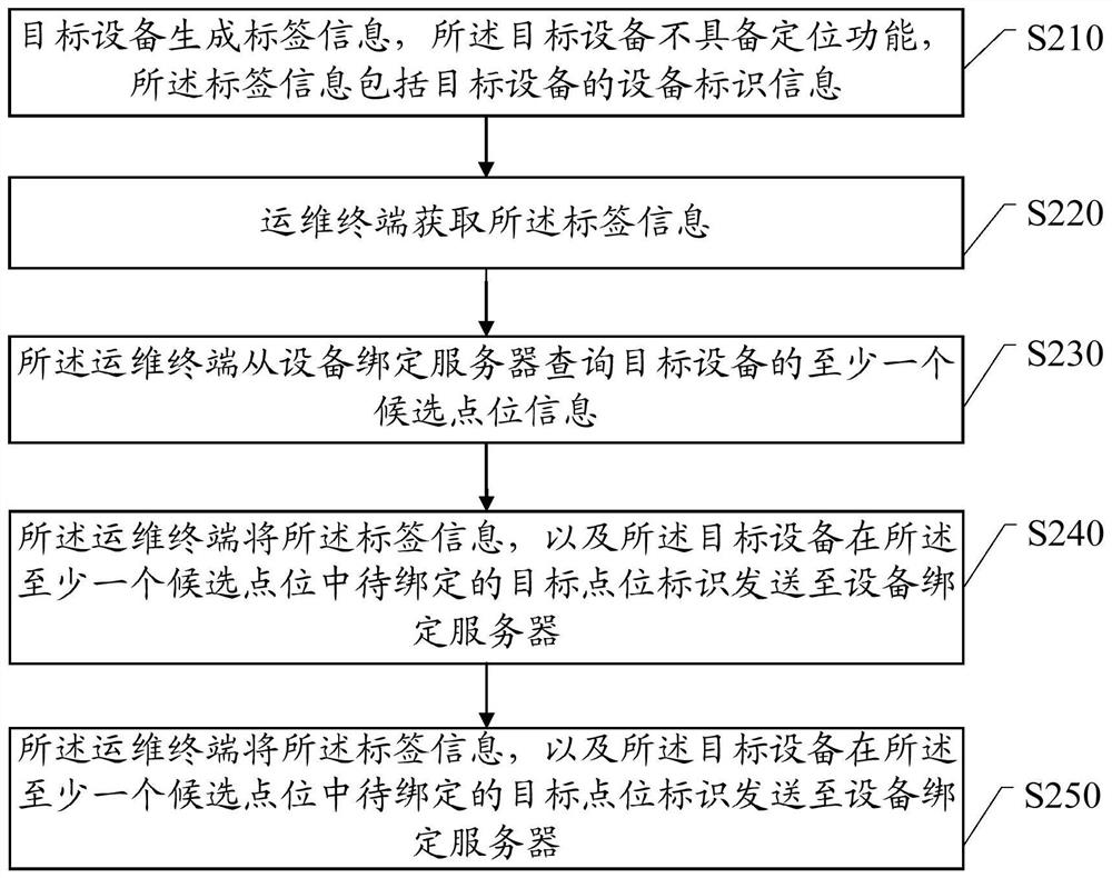
The embodiment of the invention discloses an equipment binding method, device and system, and the method comprises the steps that target equipment generates label information, the target equipment does not have a positioning function, and the label information comprises equipment identification information of the target equipment; the operation and maintenance terminal obtains the label information; the operation and maintenance terminal inquires at least one piece of candidate point location information of target equipment from an equipment binding server; the operation and maintenance terminal sends the label information and a to-be-bound target point location identifier of the target device in the at least one candidate point location to a device binding server; and the device binding server establishes a point location binding relationship of the target device based on the label information and the target point location identifier.

Description

[0001] This patent application is a divisional application of the patent application with the application number 2018112889518, the application date is October 31, 2018, and the invention name is "Device Binding Method, Device and System". technical field [0002] The present application relates to the technical field of computer software, in particular to a device binding method, device and system. Background technique [0003] In the prior art, a scenario where a certain type of equipment is deployed in large quantities is often encountered. If a location-related device is involved, the server needs to confirm the location of the device, but the device does not have a positioning function. A common practice is to specify where each device corresponds to at the factory. However, this solution needs to enter the location of the device in advance, which has low fault tolerance. Once a problem occurs with the device, it cannot be replaced with a device of the same model immed...

Claims


Application Information

Patent Timeline
Patent Type & Authority Applications(China)
IPC IPC(8): H04L67/146H04L67/52
CPCH04L67/146H04L67/52
Inventor 韩喆周乐郑梦雪杨磊
Owner ADVANCED NEW TECH CO LTD
Learn More