Novel flexible rotating and moving contact net for electrified railway

A technology for electrified railways and catenary, applied in power lines, overhead lines, transportation and packaging, etc., can solve problems such as swinging of mobile catenary, influence of installation of mobile catenary, and inability of the wrist arm to fully rotate to the side of the railway, etc., to achieve The effect of reducing operating costs, eliminating operating links, and simplifying operating procedures

Pending Publication Date: 2022-04-05
CHINA RAILWAY DESIGN GRP CO LTD +1
View PDF0 Cites 0 Cited by
  • Summary
  • Abstract
  • Description
  • Claims
  • Application Information

AI Technical Summary

Problems solved by technology

[0005] 2. In the existing catenary, the arm cannot be fully rotated to the side of the railway;
[0007] 4. The mobile catenary is located on the side of the non-railway most of the time, and only moves to the top of the railway when the container train enters or exits the freight station. The installation of the mobile catenary is affected by the geographical location. For example, strong winds will cause Will cause the mobile catenary to wobble, etc.

Method used


Image

  • Novel flexible rotating and moving contact net for electrified railway
  • Novel flexible rotating and moving contact net for electrified railway
  • Novel flexible rotating and moving contact net for electrified railway

Examples


Embodiment Construction

[0029] Reference will now be made in detail to the exemplary embodiments, examples of which are illustrated in the accompanying drawings. When the following description refers to the accompanying drawings, the same numerals in different drawings refer to the same or similar elements unless otherwise indicated. The implementations described in the following exemplary examples do not represent all implementations consistent with the present invention. Rather, they are merely examples of means consistent with aspects of the invention as recited in the appended claims.

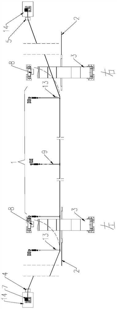
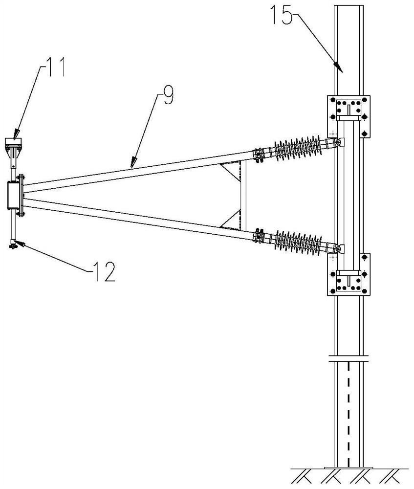
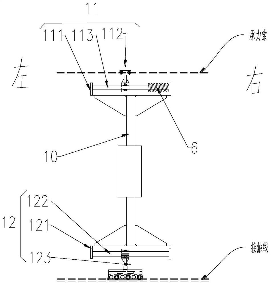
[0030] Such as figure 1 , figure 2 with image 3 As shown, this embodiment provides a new type of flexible rotating mobile catenary for electrified railways, which includes a mobile segment catenary 1, a fixed catenary 2, a door frame 3, a first weight structure 4, a second weight structure 5, a spring compensation Device 6, lifting motor 7 and electromagnetic brake device 8, wherein

[0031] The fixed caten...


PUM


Abstract

The invention relates to a novel flexible rotating and moving contact network for an electrified railway, which comprises a moving section contact network, a fixed contact network, a portal frame, a first balance weight structure, a second balance weight structure, a spring compensation device, a lifting motor and an electromagnetic band-type brake device, and the weight of the first balance weight structure acts on one end of a carrier cable and/or a contact line; the weight of the second balance weight structure acts on the other end of the carrier cable and/or the contact line; the lifting motor is arranged at one end of the moving section contact net and is used for lifting or lowering the height of the first balance weight structure; a carrier cable and/or a contact line in the movable contact net are/is controlled to move to the position above the rail or one side edge of the rail; the electromagnetic band-type brake device is arranged on the portal frame, and when the moving section contact network rotates to the side edge of a railway, the electromagnetic band-type brake device attracts the rotating cantilever closest to the portal frame; and a spring in the spring compensation device is used for converting pulling force of the carrier cable into pushing force to further push the cantilever to rotate.

Description

technical field [0001] The invention relates to the field of electrified railway mobile catenary, in particular to a novel flexible rotating mobile catenary for electrified railway. Background technique [0002] In the electrified line, the traditional catenary is fixed above the line and cannot be moved, but it occupies the loading and unloading space of the cargo loading and unloading line in the dedicated line cargo yard, resulting in the electrification of the cargo loading and unloading line, which can only be operated by internal combustion engines. This operation method has low efficiency, high cost and cumbersome procedures, which seriously restricts the cargo loading and unloading efficiency of the cargo loading and unloading line. [0003] The existing mobile catenary has the following deficiencies: [0004] 1. In the existing mobile catenary, one end uses a weight, and the other end is dragged by a motor to control the catenary to rotate to the top of the railway...

Claims


Application Information

Patent Timeline
Patent Type & Authority Applications(China)
IPC IPC(8): B60M1/20B60M1/234
Inventor 何常红朱鹏飞王国梁古晓东李少鹏李方安韩柱先李洪生林德福尹魁元陈志雄韩凌青李彦华
Owner CHINA RAILWAY DESIGN GRP CO LTD
Why Eureka
Try Eureka