Supercharge Your Innovation With Domain-Expert AI Agents!

Neutral point potential balance control method of NPC three-level DVR system

A control method and potential balance technology, which is applied to electrical components, AC network voltage adjustment, output power conversion devices, etc., can solve the working conditions of incorrect compensation, midpoint potential DC imbalance, and inability to directly apply asymmetric voltage and other problems, to achieve the effect of solving the DC balance problem and quickly equalizing the average voltage value

Active Publication Date: 2022-04-05
SUZHOU AIKE BORUI POWER SUPPLY TECH
View PDF5 Cites 1 Cited by
  • Summary
  • Abstract
  • Description
  • Claims
  • Application Information

AI Technical Summary

Problems solved by technology

How to solve the midpoint voltage unbalance problem of NPC three-level DVR in unbalance compensation mode is a big challenge
However, the zero-sequence component method will still produce fluctuations three times the output frequency within a certain range of modulation ratio and power factor
In the double modulation wave method, the modulation wave is reconstructed so that the average current sum of the midpoint within a switching cycle is zero, thereby completely eliminating the midpoint voltage fluctuation. However, the above-mentioned double modulation wave method is based on the three-level converter It is carried out under the working condition of three-phase symmetrical voltage output by the device, and the working condition of asymmetrical voltage cannot be directly applied
[0004] Aiming at the mid-point potential DC unbalance problem of the double-modulated wave method in the unbalanced compensation working condition, the traditional compensation amount calculation method, its boundary value analysis is not comprehensive enough, lacks a necessary condition, and the compensation will be incorrect in some working conditions situation, and not suitable for three-phase unsymmetrical voltage working conditions

Method used


Image

  • Neutral point potential balance control method of NPC three-level DVR system
  • Neutral point potential balance control method of NPC three-level DVR system
  • Neutral point potential balance control method of NPC three-level DVR system

Examples


Embodiment Construction

[0067] The technical solutions of the present invention will be further described below in conjunction with the accompanying drawings and specific embodiments.

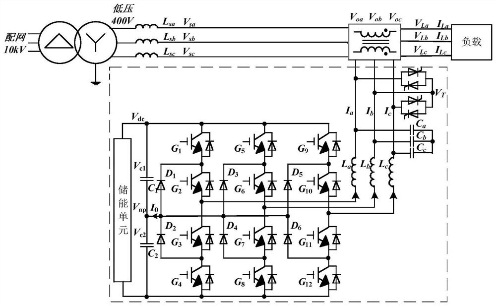
[0068] The invention provides a midpoint potential balance control method of an NPC three-level DVR system, which is based on a three-phase three-wire NPC three-level DVR system.

[0069] see figure 1 As shown, the DVR system includes: 12 IGBT devices G1~G12 ;Midpoint clamping diode D1~D ;Inverter inductance of the three-phase bridge L a 、L b 、L c ;Three-phase output high-pass filter capacitor C a 、C b 、C c ; DC side upper and lower bus capacitors C 1 、C 2 ; Bidirectional bypass thyristor section V T ;Three-phase system impedance L sa 、L sb 、L sc ;Three-phase grid voltage on the low voltage 400V side V sa 、V sb 、V sc ;Three-phase load voltage V La 、V Lb 、V Lc ;The three-phase output voltage connected in series to the power grid when the DVR is running V oa 、V ob 、V oc ;Thr...


PUM


Abstract

The invention discloses a neutral-point potential balance control method for an NPC three-level DVR system, and the method comprises the steps: carrying out the calculation of the balance compensation amount of a DC imbalance neutral-point potential under the imbalance working condition of the NPC three-level DVR system, and the calculation of an amplitude limiting range; the average voltage values of the three-phase three-wire system upper and lower bus capacitors are equal so as to eliminate the low-frequency fluctuation of the neutral-point potential and realize the balance control of the neutral-point potential of the NPC three-level DVR system. According to the method, the compensation amount is added and amplitude limiting is carried out on the compensation amount, so that the average voltage values of upper and lower bus capacitors of the three-phase three-wire system can be quickly equal, and the direct current balance problem of the three-phase three-wire NPC three-level DVR system under the unbalanced working condition is solved.

Description

technical field [0001] The invention relates to the technical field of improving the midpoint potential imbalance problem of a three-phase three-line three-level dynamic voltage restorer under unbalanced voltage sag compensation working conditions, in particular to a midpoint potential balance control method for an NPC three-level DVR system . Background technique [0002] With the continuous development of the economy, the sensitive equipment in the power distribution network has increased significantly, which puts forward more requirements for the high-quality power supply of the power grid. Problems such as voltage sags and swells are the main causes of equipment failure and serious economic losses. Dynamic voltage restorer (dynamic voltage restorer, DVR) is one of the effective means to solve the problem of voltage sag and swell. Three-level topology has been widely promoted in many fields such as flexible AC power transmission and medium voltage AC drive. The applica...

Claims


Application Information

Patent Timeline
Patent Type & Authority Applications(China)
IPC IPC(8): H02M7/487H02J3/12H02J3/26
CPCY02E40/50
Inventor 王森刘咏妮成文杰周大磊侯飞张俊奇胡江江
Owner SUZHOU AIKE BORUI POWER SUPPLY TECH
Features
  • R&D
  • Intellectual Property
  • Life Sciences
  • Materials
  • Tech Scout
  • Unparalleled Data Quality
  • Higher Quality Content
  • 60% Fewer Hallucinations
Learn More