
Noise reduction concrete mixer

A technology for a concrete mixer and a mixing mechanism, which is applied to cement mixing devices, clay preparation devices, chemical instruments and methods, etc., can solve the problems of non-contraction of the mixing device, harm to people's health, and insignificant mixing effect of the mixing device. The effect of stirring efficiency and stirring effect

Pending Publication Date: 2022-04-08
CHINA HARBOUR ENGINEERING
View PDF0 Cites 0 Cited by
  • Summary
  • Abstract
  • Description
  • Claims
  • Application Information

AI Technical Summary

Problems solved by technology

[0002] Concrete mixer is a very important part of people's construction projects. A lot of concrete materials are used in the process of building houses. These concrete materials are generally mixed with cement, lime, sand and other materials and put into the concrete mixer for a certain period of time. Due to the different proportions of the principle added to the concrete mixer, the quality of the concrete material produced is also different. Sufficient mixing is one of the necessary conditions to ensure the quality of concrete, but the mixing device of the traditional mixer is not scalable, and the mixing during work The device can’t stretch and stir while stirring, so the mixing effect is not obvious, which can’t meet the needs of the work, and the traditional mixer is not equipped with sound insulation materials, and the inside of the mixer and the motor will make a lot of noise during work. Working in a noisy environment for a long time will be harmful to people’s health. cause harm

Method used

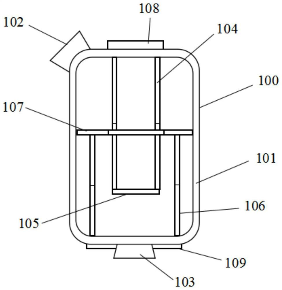
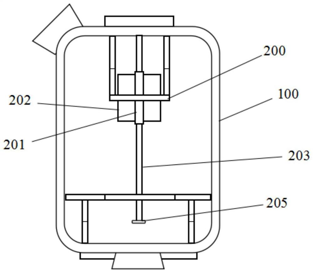

Image

  • Noise reduction concrete mixer
  • Noise reduction concrete mixer
  • Noise reduction concrete mixer

Examples


Embodiment Construction

[0019] The present invention will be described in further detail below in conjunction with the accompanying drawings and specific embodiments, so that those skilled in the art can implement it with reference to the description.

[0020] It should be understood that terms such as "having", "comprising" and "including" used herein do not exclude the presence or addition of one or more other elements or combinations thereof.

[0021] It should be noted that the experimental methods described in the following embodiments, unless otherwise specified, are conventional methods, and the reagents and materials, if not otherwise specified, can be obtained from commercial sources; in the description of the present invention, It should be noted that, unless otherwise clearly stipulated and limited, the terms "installation", "connection" and "arrangement" should be interpreted in a broad sense, for example, it can be fixedly connected, arranged, or detachably connected, arranged, or Connec...


PUM


Abstract

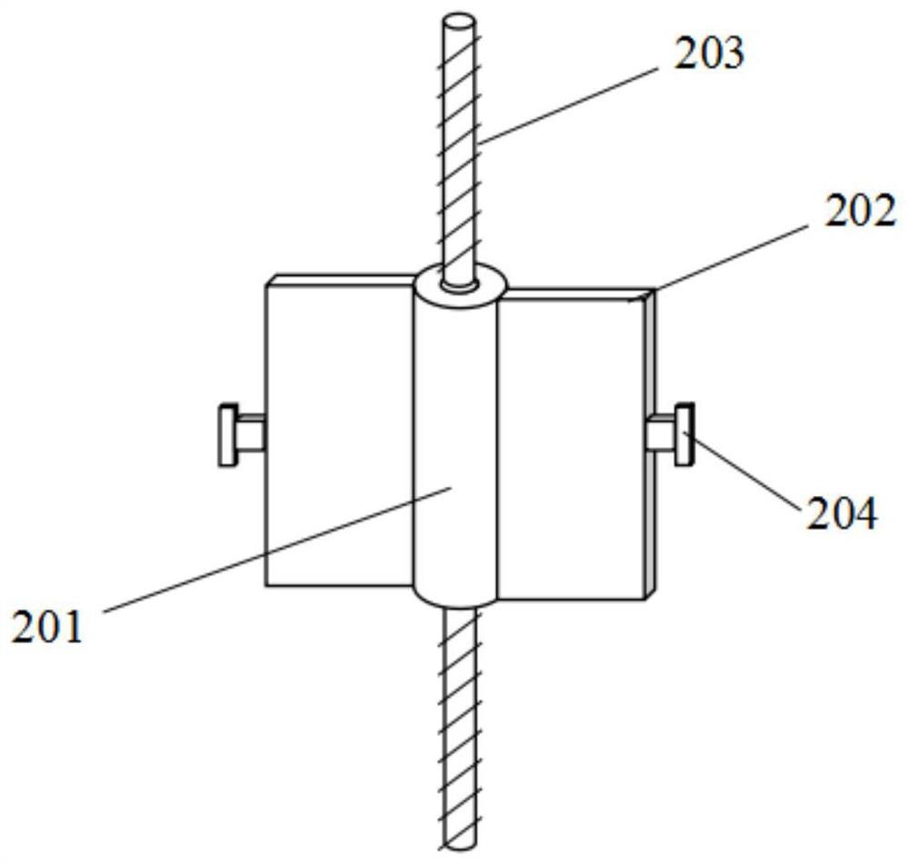
The invention discloses a noise reduction concrete mixer, which comprises: a mixing tank having a double-layer wall structure, a cavity gap formed by the double-layer wall being filled with a sound absorption and noise reduction material, the mixing tank also being provided with a feed port and a discharge port; the stirring mechanism is arranged in the stirring tank body, the stirring mechanism comprises a first stirring part and a second stirring part, the first stirring part comprises a plurality of first lifting rods extending downwards from the inner top wall of the stirring tank body, and the end parts of the plurality of first lifting rods are connected with discharging pieces; the second stirring part comprises a plurality of second lifting rods extending upwards from the inner bottom wall of the stirring tank body, the ends of the second lifting rods are connected with a discharging ring, a through hole allowing the discharging piece to penetrate through in a matched mode is formed in the middle of the discharging ring, each first lifting rod is connected with a first synchronous motor, and each second lifting rod is connected with a second synchronous motor. And each second lifting rod is connected with a second synchronous motor. The two groups of stirring parts move relatively up and down, so that concrete is stirred.

Description

technical field [0001] The invention relates to the technical field of construction equipment. More specifically, the present invention relates to a noise reducing concrete mixer. Background technique [0002] Concrete mixer is a very important part of people's construction projects. A lot of concrete materials are used in the process of building houses. These concrete materials are generally mixed with cement, lime, sand and other materials and put into the concrete mixer for a certain period of time. Due to the different proportions of the principle added to the concrete mixer, the quality of the concrete material produced is also different. Sufficient mixing is one of the necessary conditions to ensure the quality of concrete, but the mixing device of the traditional mixer is not scalable, and the mixing during work The device can’t stretch and stir while stirring, so the mixing effect is not obvious, which can’t meet the needs of the work, and the traditional mixer is n...

Claims


Application Information

Patent Timeline
IPC IPC(8): B28C5/48B28C5/08B28C5/16
Inventor 杨双喜李鹏琳许程光
Owner CHINA HARBOUR ENGINEERING
Learn More