Foot bath device

A foot bath and soft glue technology, applied in the field of foot bath, can solve the problems such as low one-time success rate and disadvantage of the folding operation of the foldable and foldable foot bath, so as to improve the use experience and improve the one-time success rate. Effect

Pending Publication Date: 2022-04-12
佛山市星曼信息科技有限公司
View PDF0 Cites 0 Cited by
  • Summary
  • Abstract
  • Description
  • Claims
  • Application Information

AI Technical Summary

Problems solved by technology

[0002] In the process of realizing the present invention, the inventor found that, for a foldable footbath with a soft rubber side wall on the side of the foot bath cavity, in the normal process of pressing down the basin body to fold the soft rubber side wall, due to the soft rubber The side wall is soft and prone to deformation that is not conducive to normal compression. For example, in the process of folding the soft rubber side wall from top to bottom, the upper part of the soft rubber side wall needs to be gradually bent. The outer side can be folded smoothly, but when the soft rubber side wall deforms irregularly during the folding process, for example, when the soft rubber side wall is still in the upper part of the fold, the middle area will protrude outward first, resulting in the upper part of the soft rubber side wall Some parts cannot continue to bend downwards, so the folding cannot be completed, resulting in a low one-time success rate of the folding operation of the foldable foot bath

Method used


Image

  • Foot bath device
  • Foot bath device
  • Foot bath device

Examples


specific Embodiment 1

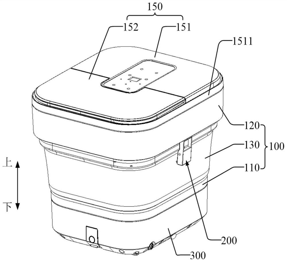
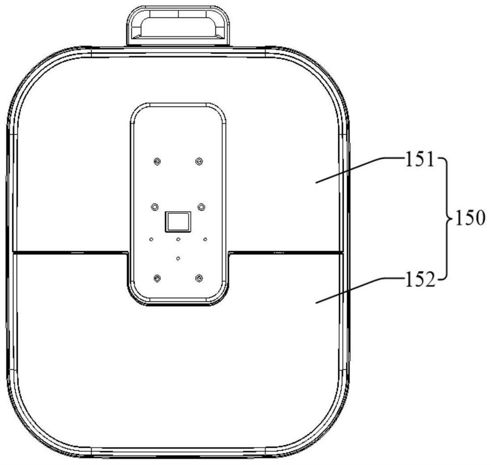
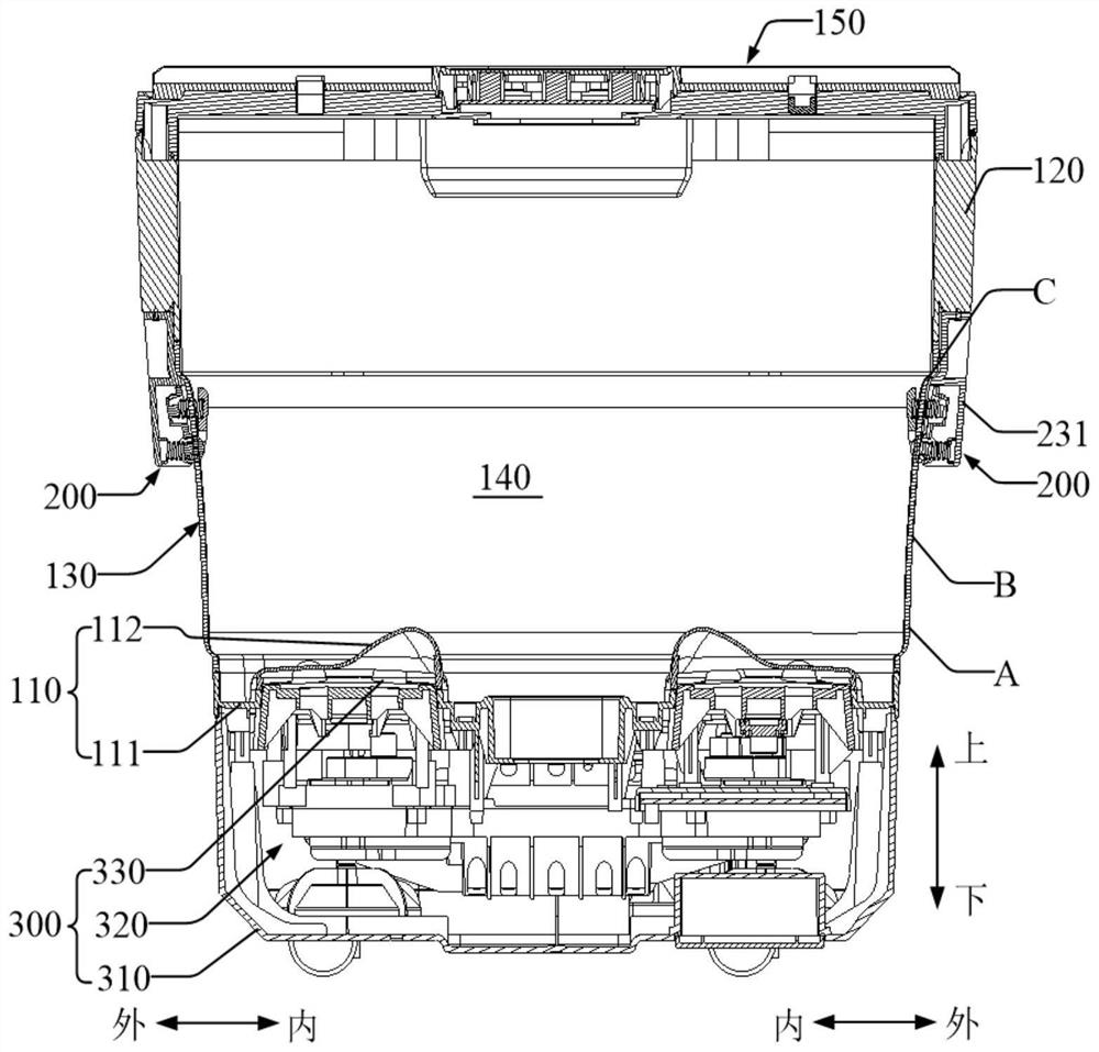
[0060] Specific embodiment 1 (as Figure 1 to Figure 5 shown):

[0061] Such as Figure 4 and Figure 5 As shown, the elastic compression structure 200 includes a first bracket A211 and a first elastic member A212.

[0062] The first bracket A211 is rotatably connected and provided. And at least a part of the first bracket A211 is located at the outer side of the soft rubber side wall 130; the first elastic member A212 cooperates with the first bracket A211, wherein, when the soft rubber side wall 130 is unfolded, the soft rubber side wall 130 and the first bracket The contact of A211 makes the first elastic member A212 compressed, and the elastic force of the first elastic member A212 can be used to drive the first bracket A211 to rotate when the soft rubber side wall 130 is folded, so that the first bracket A211 can be rotated along the F direction by Squeeze the outer surface of the soft rubber side wall 130 from outside to inside.

[0063] It can be understood that, f...

specific Embodiment 2

[0086] Specific embodiment 2 (as Figure 6 to Figure 8 shown):

[0087] combine Figure 6 and Figure 7 It can be understood that the elastic compression structure 200 includes a first bracket B221 , a third bracket 231 and a first elastic member B222 .

[0088] The third bracket 231 is connected to the upper connecting member, and a part of the third bracket 231 extends downward to the outer side of the soft rubber side wall 130 . The third bracket 231 is recessed with a groove 2312 opening toward the soft rubber side wall 130 . The lower end of the first bracket B221 protrudes into the groove 2312, and is rotatably connected to the sidewall of the groove 2312 via shafts and holes. The upper end of the first support B221 is a movable end, and the upper end of the first support B221 is provided with rollers 223, and the quantity of the rollers 223 can be as follows Figure 8 The one shown in , can also be set to multiple (such as 2, 3, 4, etc.) based on requirements. The...

specific Embodiment 3

[0094] Specific embodiment 3 (as Figure 9 to Figure 12 shown):

[0095] combine Figure 10 and Figure 11 It can be understood that the elastic compression structure 200 is located on the outside of the soft rubber side wall 130 and includes a fourth bracket 241 and a first elastic piece 242 .

[0096] The fourth bracket 241 is connected to the upper connecting piece, and is extended from the upper connecting piece such that a part of the fourth bracket 241 extends to the outer side of the soft rubber side wall 130 . Of course, based on the fact that the elastic pressing structure 200 is located inside the soft rubber sidewall 130 , a part of the fourth bracket 241 can extend to the position inside the soft rubber sidewall 130 .

[0097] Such as Figure 11 and Figure 12 As shown, the fourth bracket 241 is provided with an engaging portion 2412 for engaging with an upper connecting member (such as the side housing 120 or the side cover 1511 of the fixing cover 151 ). Th...


PUM


Abstract

The invention provides a foot bath device which comprises a foldable basin body, the foldable basin body comprises a basin bottom, an upper connecting piece and a soft rubber side wall capable of being folded or unfolded, the soft rubber side wall is connected between the basin bottom and the upper connecting piece in a transition mode, and when the soft rubber side wall is unfolded, a foot bath cavity is defined by the soft rubber side wall and the basin bottom; the elastic pressing structure can apply elastic force to the soft rubber side wall, and the elastic force is used for limiting the part, where the elastic force is applied, of the soft rubber side wall from protruding outwards to deform or sinking inwards to deform in the folding process of the soft rubber side wall. According to the technical scheme, bad deformation of the soft rubber side wall can be limited and corrected to a certain extent according to requirements, so that the deformation direction of the soft rubber side wall in each compression and folding process tends to be standard according to preset setting, the one-time success rate of folding operation is improved, and the use experience of a user is greatly improved.

Description

technical field [0001] The application relates to the field of foot massage equipment, in particular to a foot bath. Background technique [0002] In the process of realizing the present invention, the inventor found that, for a foldable footbath with a soft rubber side wall on the side of the foot bath cavity, in the normal process of pressing down the basin body to fold the soft rubber side wall, due to the soft rubber The side wall is soft and prone to deformation that is not conducive to normal compression. For example, in the process of folding the soft rubber side wall from top to bottom, the upper part of the soft rubber side wall needs to be gradually bent. The outer side can be folded smoothly, but when the soft rubber side wall deforms irregularly during the folding process, for example, when the soft rubber side wall is still in the upper part of the fold, the middle area will protrude outward first, resulting in the upper part of the soft rubber side wall The pa...

Claims


Application Information

Patent Timeline
IPC IPC(8): A47K3/062A61H39/04
Inventor 肖移龙莫润超欧阳杰鹏谢慧皇
Owner 佛山市星曼信息科技有限公司
Why Eureka
Try Eureka