Industrial wood board cutting equipment
A kind of cutting equipment and industrial technology, applied in the field of industrial wood cutting equipment, can solve the problems of manpower consumption, cumbersome operation process, operator cuts, etc., and achieve the effect of simple operation, ensuring safety and saving manpower
- Summary
- Abstract
- Description
- Claims
- Application Information
AI Technical Summary
Problems solved by technology
Method used
Image

Examples
Embodiment 1
[0028] An industrial board cutting equipment such as Figure 1-3 As shown, it includes a base plate 1, a slide bar 2, a slide block 3, a cutting knife 4, a transmission mechanism 5 and a first clamping mechanism 6. A slide bar 2 is connected to the front side of the top of the base plate 1, and a A slider 3, a cutting knife 4 is connected to the slider 3, a transmission mechanism 5 is arranged on the slider 2, and a first clamping mechanism 6 is arranged on the bottom plate 1.
[0029] The transmission mechanism 5 includes a first support plate 51, a support frame 52, a motor 53, a sprocket wheel 54, a chain 55, a first rotating shaft 56, a belt drive group 57, missing gears 58, full gears 59, a second rotating shaft 510, and a transmission belt 511 and transport belt 512, the right side of the slide bar 2 is connected with a first support plate 51, the first support plate 51 is connected with the bottom plate 1, the bottom of the first support plate 51 is connected with a sup...
Embodiment 2
[0033] On the basis of Example 1, such as Figure 4 and Figure 6 As shown, it also includes a blanking mechanism 9 and a loading mechanism 7, the bottom plate 1 is provided with a blanking mechanism 9, and the blanking mechanism 9 is provided with a loading mechanism 7.
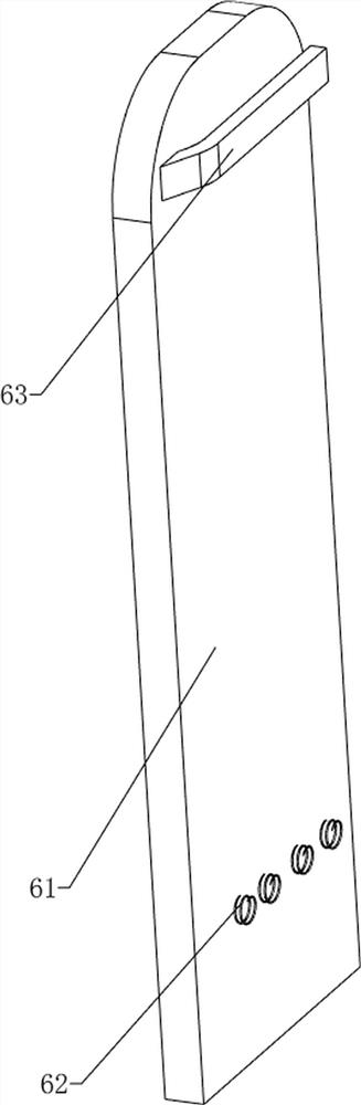
[0034] The blanking mechanism 9 includes a charging frame 91, a cover 92 and a torsion spring 93. The rear side of the bottom plate 1 top is connected with a charging frame 91, and the top of the charging frame 91 is rotatably connected with a cover 92. Between the cover 92 and the charging frame 91 A torsion spring 93 is connected between them.
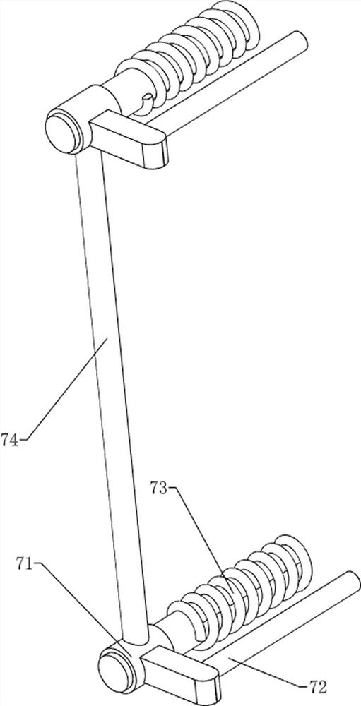
[0035] The feeding mechanism 7 includes a support column 71, an extruding rod 72, a second spring 73 and a first push rod 74. The rear side of the loading frame 91 is slidingly connected with two support columns 71, and the support column 71 is connected with an extrusion Rod 72, extruding rod 72 and charging frame 91 sliding fit, are connected with the first pus...
Embodiment 3
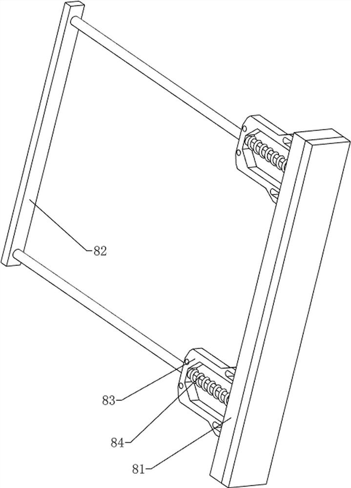
[0038] On the basis of Example 2, such as Figure 5 As shown, it also includes a second clamping mechanism 8, the second clamping mechanism 8 includes a squeeze plate 81, a second push rod 82, a block 83 and a third spring 84, and the right side of the loading frame 91 is connected with a squeeze Pressing plate 81, clamping blocks 83 are connected to both sides of the pressing plate 81, a second push rod 82 is slidably connected between the two clamping blocks 83, and a third spring is connected between the second push rod 82 and the clamping block 83 84, the second push rod 82 is slidingly matched with the extrusion plate 81, and the second push rod 82 extends into the charging frame 91.
[0039] When the plank needs to be placed, the second push rod 82 can be pulled to move to the right, the third spring 84 is compressed, and after the second push rod 82 moves to the right, the plank can be placed. After placing the plank, release the second push rod 82, under the action of...
PUM
 Abstract
Description
Claims
Application Information
 - R&D Engineer
- R&D Manager
- IP Professional
- Industry Leading Data Capabilities
- Powerful AI technology
- Patent DNA Extraction
Browse by: Latest US Patents, China's latest patents, Technical Efficacy Thesaurus, Application Domain, Technology Topic.
© 2024 PatSnap. All rights reserved.Legal|Privacy policy|Modern Slavery Act Transparency Statement|Sitemap