Injection mold with controllable thrust

An injection mold and thrust technology, applied in the field of molds, can solve the problems of large thrust of the cylinder and wear of plastic products, and achieve the effect of simple structure, low production cost and no noise

Pending Publication Date: 2022-04-12
东莞晶彩光学有限公司
View PDF5 Cites 0 Cited by
  • Summary
  • Abstract
  • Description
  • Claims
  • Application Information

AI Technical Summary

Problems solved by technology

In the injection mold of the prior art, a cylinder is usually used to drive the ejector pin to eject the plastic product from the mold cavity. Due t

Method used


Image

  • Injection mold with controllable thrust
  • Injection mold with controllable thrust
  • Injection mold with controllable thrust

Examples


Embodiment Construction

[0019] The present invention will be further described in detail below with reference to the examples and drawings, but the implementation of the present invention is not limited thereto.

[0020] Such as Figure 1-4 Shown:

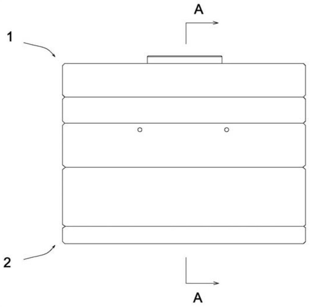
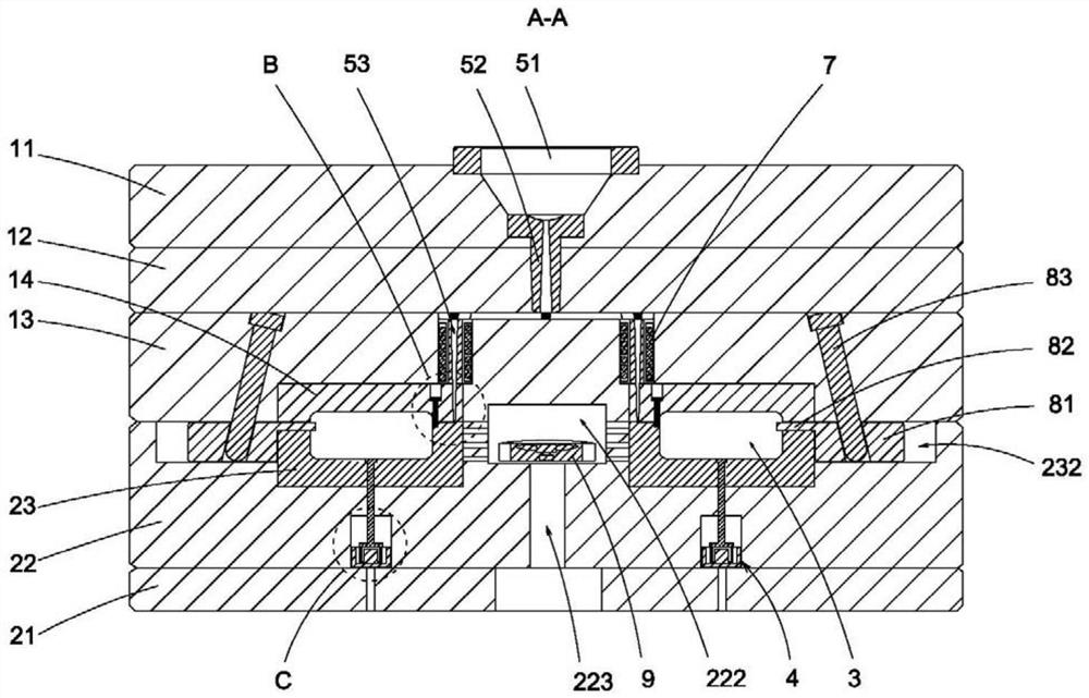
[0021] An injection mold with controllable thrust comprises an upper mold 1 and a lower mold 2. The upper mold 1 includes a top plate 11, an upper backing plate 12 fixed on the lower side of the top plate 11, an upper pressing plate 13 fixed on the lower side of the upper backing plate 12, The upper mold core 14 fixed on the lower end of the upper platen 13, the lower mold 2 includes a bottom plate 21, a lower backing plate 22 on the upper side of the fixed bottom plate 21, a lower mold core 23 fixed on the upper end of the lower backing plate 22, the upper mold core 14 and the lower mold core Form cavity 3 between 23, be provided with groove 221 in lower backing plate 22, be provided with magnetic force ejector assembly 4 in groove 221, magnetic force e...


PUM


Abstract

The thrust-controllable injection mold comprises an upper mold body and a lower mold body, the upper mold body comprises a top plate, an upper base plate, an upper pressing plate and an upper mold core, the lower mold body comprises a bottom plate, a lower base plate and a lower mold core, a mold cavity is formed between the upper mold core and the lower mold core, a groove is formed in the lower base plate, a magnetic material ejecting assembly is arranged in the groove, and the magnetic material ejecting assembly is arranged in the mold cavity. The magnetic ejection assembly comprises U-shaped iron fixed to the bottom of the groove, a magnet fixed to the inner side of the U-shaped iron, a coil located on the inner side of the U-shaped iron and arranged on the outer side of the magnet in a sleeving mode and an ejector pin connected to the upper end of the coil, and the upper end of the ejector pin can extend to the inner side of the cavity. According to the injection mold, a traditional air cylinder ejection device is changed into the magnetic ejection assembly, thrust can be better controlled, no noise is generated in the material pushing process, the structure is simple, and the manufacturing cost is low.

Description

technical field [0001] The invention relates to the technical field of molds, in particular to an injection mold with controllable thrust. Background technique [0002] Injection molds are common equipment in the industrial field, mainly used to produce plastic products. The injection molds of the prior art usually use a cylinder to drive the thimble to eject the plastic product from the mold cavity. Due to the large thrust of the cylinder, the thimble is easy to cause wear on the surface of the plastic product, which has a relatively large defect. Contents of the invention [0003] In view of the above problems, the present invention provides an injection mold with controllable thrust. The traditional cylinder ejector is changed into a magnetic ejector assembly, which can better control the thrust, and there is no noise during the ejection process. The structure is simple and easy to manufacture. low cost. [0004] To achieve the above object, the present invention solv...

Claims


Application Information

Patent Timeline
IPC IPC(8): B29C45/26B29C45/33B29C45/40B29C45/44
Inventor 谭沿河姚雅兰
Owner 东莞晶彩光学有限公司
Why Eureka
Try Eureka