Surface profile measurement

a surface profile and measurement technology, applied in distance measurement, surveying and navigation, instruments, etc., can solve the problems of limiting the application of such systems to the remote, increasing the obtuse line of sight of incident light patterns and cameras, and relatively expensive implementation

Inactive Publication Date: 2010-11-16
INSTRO PREC
View PDF10 Cites 49 Cited by
  • Summary
  • Abstract
  • Description
  • Claims
  • Application Information

AI Technical Summary

Benefits of technology

[0031]The shutter arrangement enables the distance measurement (and the subsequent profile calculation) to be free from noise from other scattering sources.

Problems solved by technology

As a result, practical considerations tend to limit the application of such systems to remote objects no more than a few metres away.
In addition, as the baseline is lengthened, the angle between the incident light pattern and the line of sight of the camera becomes more obtuse and shadows cast by features in the remote object can obscure the 3D profile measurement.
This scanned LRF approach does not suffer from the range limitations of the structured light approach, but is relatively expensive to implement because high precision and costly components are required for good accuracy.
In addition, because the whole mass of the distance measuring device is scanned, achieving scanning at rates sufficient to give “real time” 3D image data is problematic.
These approaches work well for relatively short ranges, but require much higher levels of illumination power to work at ranges of many kilometres.
A further factor affecting long range surface profile measurement is the effect of atmospheric turbulence, as this causes the apparent position of the far object being examined to move with time.
However, it will be recognised that very short exposure times are required; for example to get a depth resolution of 0.5 m an exposure time and time delay stability of around 3.3 nS are required which requires very expensive and specialised hardware to achieve.
In addition, because the exposure time is so short, a very high intensity illumination source (albeit for a short period) is required, which is also expensive.
The significant technical and commercial challenges involved make implementing this approach very difficult.

Method used


Image

  • Surface profile measurement
  • Surface profile measurement
  • Surface profile measurement

Examples


Embodiment Construction

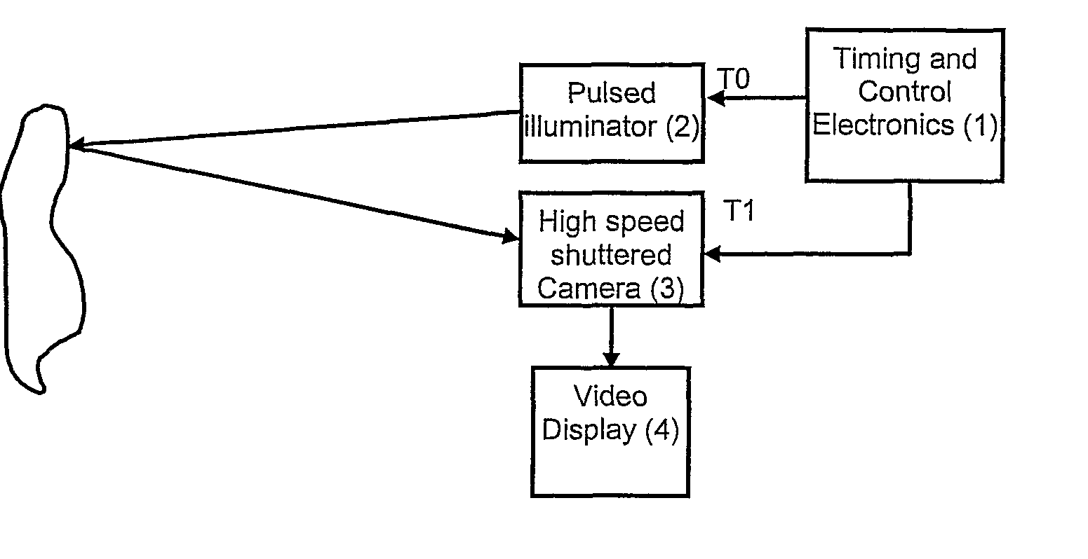
[0042]The invention provides a 3D imaging system which is specifically adapted for use with targets at long range, and which uses a stationary receiving optical system.

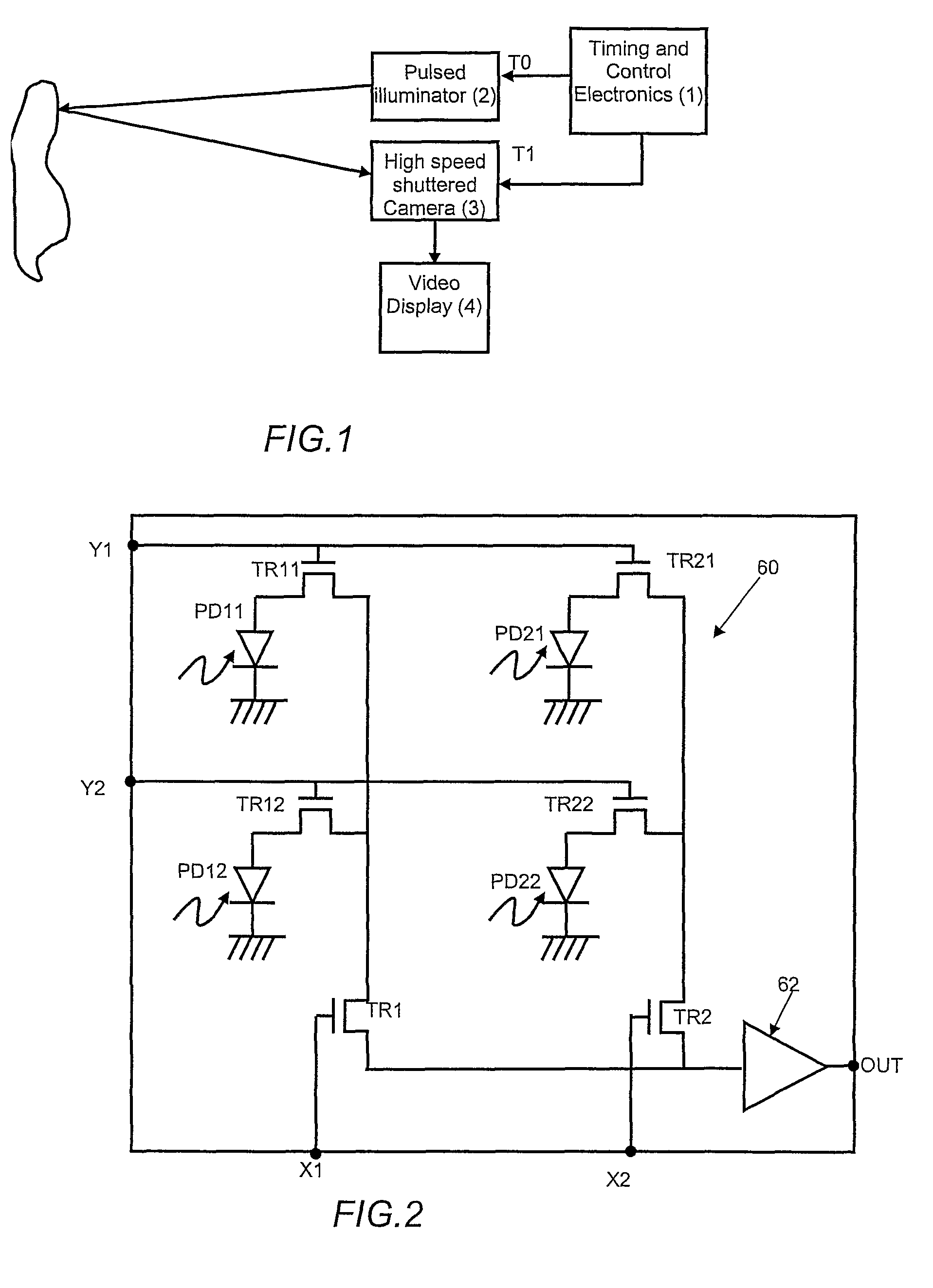
[0043]The invention uses a two dimensional detector, which will first be described with reference to FIG. 2.

[0044]FIG. 2 is a simplified schematic of a photodiode array for use in an imaging system of the invention, in a 2×2 format. The device consists of an array of photodiode pixels 60, each of which comprises a photodiode (PD11 to PD22) and associated transistor (TR11 to TR22), which are configured and drive to act as analogue switches. For standard video imaging applications, the device is operated in an integration mode where incident illumination is focussed upon its surface. The incident illumination generates charge within each photodiode by the photoelectric effect. During this integration period, connections X1, X2, Y1 and Y2 are all held low so that all transistors are off and the photodiodes are electrical...


PUM


Abstract

An imaging system has a transmission system (2) for transmitting a modulated optical signal and a reception system (3) for receiving a received optical signal which is a reflected and delayed version of the transmitted signal. The reception system includes a controllable shutter arrangement for allowing reception in a controllable time window. A memory (4) collects reception data derived from different time windows, and a measure of distance is obtained corresponding to a maximum correlation between the received optical signal and the timing of the controllable time window. Surface profile information is derived from multiple distance measurements.The shutter arrangement enables the distance measurement (and the subsequent profile calculation) to be free from noise from other scattering sources.

Description

[0001]The present patent application is a non-provisional application of International Application No. PCT / GB2005 / 004612, filed Dec. 2, 2005.FIELD OF THE INVENTION[0002]The invention relates to apparatus for measuring the surface profile of a sample, and in particular relates to non-contact 3D surface profile measurement systems.BACKGROUND OF THE INVENTION[0003]The non-contact measurement of three-dimensional (3D) objects to extract data regarding their physical form and location in space is a topic which has excited much research. Many techniques have been developed to suit the distance to the object, the precision with which the object's features need to be measured and so on.[0004]One common technique is to illuminate the remote object with a light source of known pattern; so called “structured illumination”. A camera is located some distance away from the structured light source and arranged to collect an image of the projection of the structured light pattern onto the surface o...

Claims


Application Information

Patent Timeline
Patent Type & Authority Patents(United States)
IPC IPC(8): G01C3/08G01S17/08G01S17/18G01S17/89
CPCG01S17/08G01S17/107G01S17/89G01S17/18
Inventor MORCOM, CHRISTOPHER JOHN
Owner INSTRO PREC
Why Eureka
Try Eureka