Circulation flowing pulsating heat pipe for cooling electronic device

A technology for pulsating heat pipes and electronic devices, which is applied to electric solid devices, cooling/ventilation/heating renovation, electrical components, etc., can solve the problem of not being able to supply liquid to the heating section, and achieve convenient processing, low thermal resistance, and noiseless operation. Effect

Inactive Publication Date: 2005-10-19
CENT SOUTH UNIV
View PDF0 Cites 47 Cited by
  • Summary
  • Abstract
  • Description
  • Claims
  • Application Information

AI Technical Summary

Problems solved by technology

As a result, when the heat absorption of the heat-absorbing section is large, the heating section will not receive sufficient liquid supply due to the limit of capillary force

Method used


Image

  • Circulation flowing pulsating heat pipe for cooling electronic device
  • Circulation flowing pulsating heat pipe for cooling electronic device
  • Circulation flowing pulsating heat pipe for cooling electronic device

Examples


Embodiment Construction

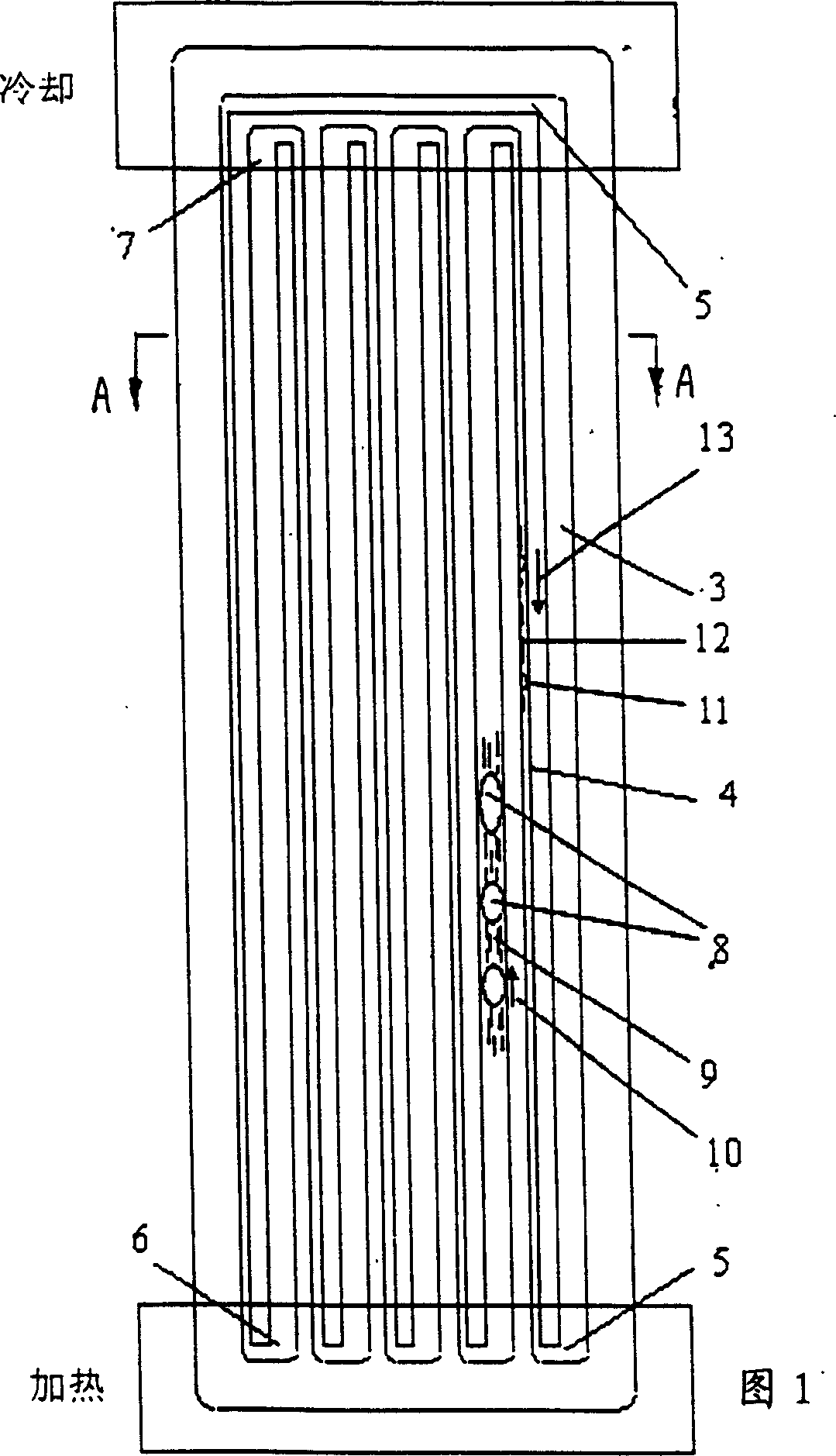
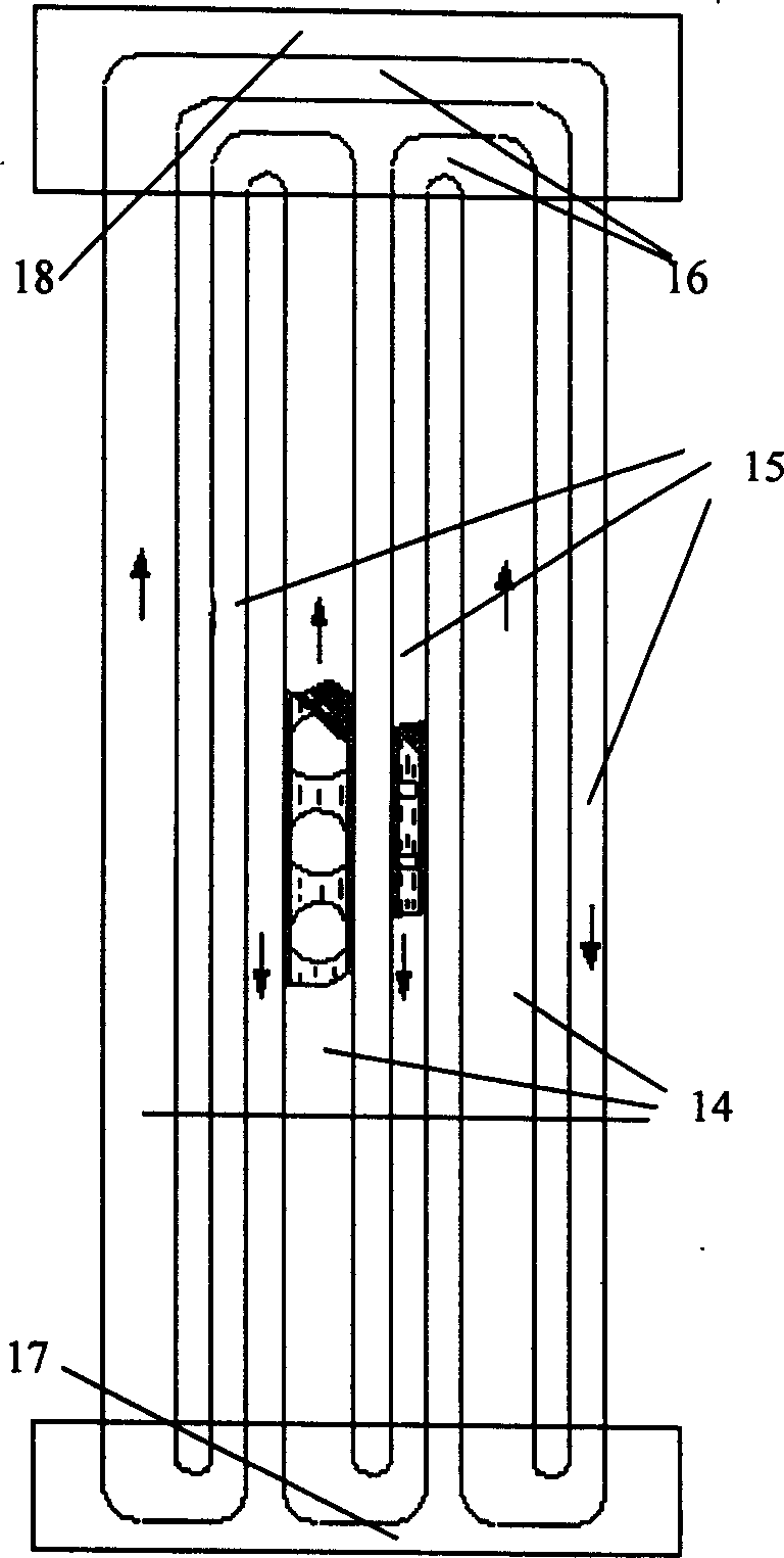
[0016] figure 1, figure 2 The structure of the pulsating heat pipe of the present invention is described. The pulsating heat pipe is composed of an aluminum unit plate 1 and a flat plate 2; one side of the aluminum unit plate 1 is milled with a group of thick straight tubes 3 arranged parallel to each other, a group of thin straight tubes 4 and a group of connecting curved channels 5. Capillary groove; the flat plate 2 covers the unit plate 1, and thus the capillary groove forms a closed cavity; the closed cavity is filled with 30% to 70% of the working fluid; the curved channel 5 at one end serves as the heating section 6 of the heat pipe, and the curved channel 5 at the other end The curved passage 5 serves as the heat dissipation section 7 of the heat pipe; the passage between the heating section 6 and the heat dissipation section 6 serves as the heat insulation section of the heat pipe.

[0017] When the pulsating heat pipe of the present invention is in operation, the he...


PUM


Abstract

This invention relates to a circulation flow pulsation thermal tube suitable for cooling spare part of semiconductor devices and other solid devices composed of two connected and mutually parallel-arrayed thick straight channel and thin straight channel, two adjacent channels are connected by an angle pipe. A heat conduction working solution forms a single-way plug flowing under the pressure generated by heat action in the channel, which absorbs heat and evaporates at the heating section and discharges heat and condenses at the radiation section. This invented pulsation thermal tube has high conduction limit and low resistance.

Description

Technical field: [0001] The invention belongs to the technical field of electronic cooling, and relates to components for cooling semiconductors or other solid devices. Background technique: [0002] With the continuous development of electronic assembly technology, the physical size of components is getting smaller and smaller, and the assembly density is increased; the performance of chips is improved, and the heat generated by them is also increased accordingly, resulting in the formation of high heat density of electronic devices. Therefore, it is more and more important to find effective heat dissipation methods for electronic devices. [0003] The conventional heat dissipation method mainly relies on the heat sink on the radiator to dissipate heat through heat conduction, which cannot meet the heat dissipation requirements of high heat flux. [0004] As shown in Figure 4: the circulation type heat pipe is a serpentine pipe, and its two ends are sealed and connected to...

Claims


Application Information

Patent Timeline
Patent Type & Authority Applications(China)
IPC IPC(8): F28D15/02H01L23/427H05K7/20
CPCF28D15/0266
Inventor 曹小林郑平晏刚
Owner CENT SOUTH UNIV
Why Eureka
Try Eureka