A secondary core evaporator and its application

A secondary core and evaporator technology, applied in indirect heat exchangers, lighting and heating equipment, etc., can solve problems such as large thermal conductivity, weakened back heat conduction, and worsening system operating conditions, so as to reduce back heat conduction, Effect of reducing backflow resistance and reducing contact thermal resistance

Active Publication Date: 2017-12-22
HUAZHONG UNIV OF SCI & TECH
View PDF1 Cites 0 Cited by
  • Summary
  • Abstract
  • Description
  • Claims
  • Application Information

AI Technical Summary

Problems solved by technology

Since the shell of the evaporator is generally made of metal materials, the thermal conductivity is relatively large, and the back heat conduction effect through the side wall and capillary core cannot be avoided.
CN201310700409.X proposes a double-capillary evaporator, which has a certain weakening effect on the back heat conduction, but it still has the following problems: the back heat conduction cannot be completely eliminated; the interior of the compensation chamber may still be in a vapor-liquid two-phase In the coexistence state, the air bubbles are generated and annihilated periodically in the compensation chamber, and its temperature and pressure are constantly fluctuating, which will cause the instability of the system operation; in addition, the air bubbles will submerge the outlet of the liquid pipeline, blocking the outlet of the liquid pipeline and causing supercooling Liquid backflow is difficult, further deteriorating the operating conditions of the system

Method used


Image

  • A secondary core evaporator and its application
  • A secondary core evaporator and its application
  • A secondary core evaporator and its application

Examples


Embodiment Construction

[0029] In order to make the object, technical solution and advantages of the present invention clearer, the present invention will be further described in detail below in conjunction with the accompanying drawings and embodiments. It should be understood that the specific embodiments described here are only used to explain the present invention, not to limit the present invention. In addition, the technical features involved in the various embodiments of the present invention described below can be combined with each other as long as they do not constitute a conflict with each other.

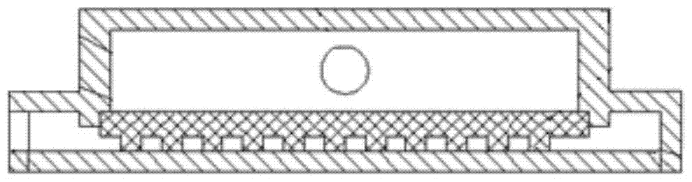
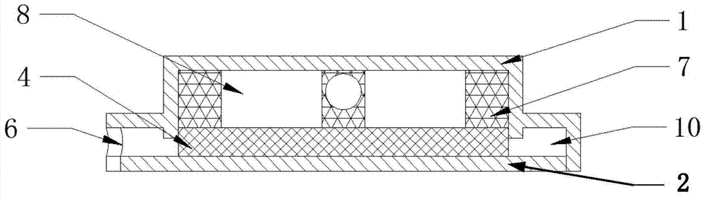
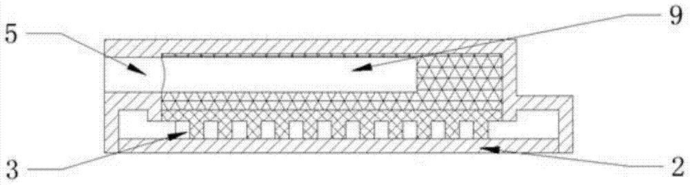
[0030] Such as figure 2 and 3 As shown, the secondary wick evaporator according to the embodiment of the present invention mainly includes four parts: an upper body 1 , a lower end cover 2 , a main capillary wick 4 and a secondary wick 7 . Among them, the upper body and the lower end cover are connected by welding to form a closed space; the main capillary core 4 and the secondary core 7 are ...


PUM


Abstract

The invention discloses a secondary core evaporator and application thereof. The secondary core evaporator comprises an upper body, a lower end cover, a main capillary core and a secondary core, wherein the upper body is connected with the lower end cover, and is provided with an inlet and an outlet; the inlet is connected with a liquid pipeline provided with multiple holes in the tail end; the main capillary core and the secondary core are accommodated in a closed space, and are respectively and tightly contacted with the lower end cover and the upper body; the secondary core has an annular structure; a straight rib for dividing the secondary core into two cavities is radially distributed along the annular structure in the secondary core; the cavities serve as compensation cavities for storing working mediums; a hole way is formed in the straight rib; the tail end of the liquid pipeline is directly inserted into the hole way; a steam groove way is formed in the main capillary core; and a space surrounded by the periphery of the steam groove way, the upper body and the lower end cover serves as a steam collecting cavity for collecting steam. The secondary core evaporator reduces the backflow resistance, the contact heat resistance and the back heat conduction of supercooling liquid, lowers the temperature of the compensation cavities, improves the system power, and improves the heat transfer limitation.

Description

technical field [0001] The invention belongs to the field of flat loop heat pipes, and more specifically relates to a secondary core evaporator applied in a flat loop heat pipe system (Flat Loop Heat Pipe: FLHP), which is suitable for use as a heat sink for high heat flow electronic devices. Cooling of control devices such as LEDs, fuel cells, etc. Background technique [0002] LHP is a separate heat pipe, which has the advantages of large heat transfer, flexible pipeline layout, and no moving parts. It has broad application prospects in aerospace thermal control and ground high heat flow electronic device cooling. LHP is mainly composed of evaporator, steam / liquid pipeline, condenser, etc. The capillary core is built in the evaporator, and the cavity between the shell of the evaporator forms a compensation cavity. Its working principle is: one surface of the evaporator is closely attached to the wall of the equipment that needs to dissipate heat, and the waste heat generat...

Claims


Application Information

Patent Timeline
Patent Type & Authority Patents(China)
IPC IPC(8): F28D15/02
CPCF28D15/02
Inventor 刘志春何松刘伟杨金国赵靖
Owner HUAZHONG UNIV OF SCI & TECH
Why Eureka
Try Eureka