Porous structure layer for heat pipe and its making process

A porous structure and heat pipe technology, applied in indirect heat exchangers, lighting and heating equipment, instruments, etc., can solve problems such as dry burning, damage to heat pipes, and inability to replenish evaporated liquid quickly, achieving low return flow resistance, improved performance, and high The effect of capillary force

Inactive Publication Date: 2008-06-18
FU ZHUN PRECISION IND SHENZHEN +1
View PDF7 Cites 2 Cited by
  • Summary
  • Abstract
  • Description
  • Claims
  • Application Information

AI Technical Summary

Problems solved by technology

When the heat absorbed by the heat-absorbing end of the heat pipe increases, the evaporation speeds up, but the speed of the liquid decreases due to the backflow resistance, and the evaporated liquid at the heat-absorbing end cannot be quickly replenished.
It is easy to cause dry burning and damage the heat pipe

Method used


Image

  • Porous structure layer for heat pipe and its making process
  • Porous structure layer for heat pipe and its making process
  • Porous structure layer for heat pipe and its making process

Examples


Embodiment Construction

[0018] The present invention will be further described below in conjunction with the embodiments with reference to the accompanying drawings.

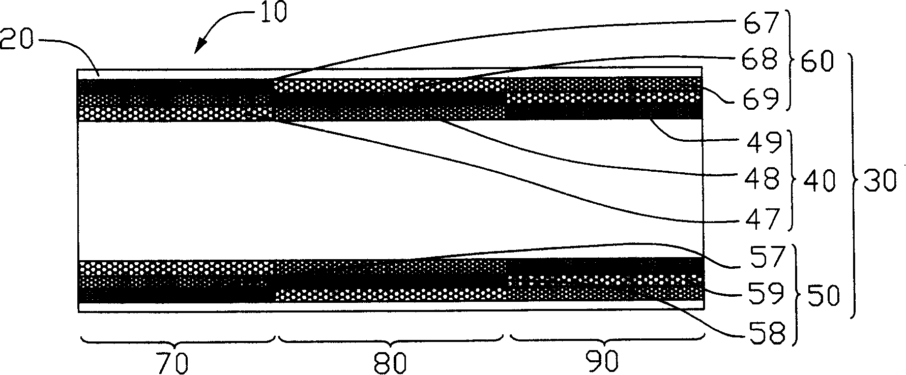
[0019] Such as figure 1 As shown, the heat pipe 10 of the present invention includes a pipe body 20 , a porous structure layer 30 in close contact with the inner wall of the pipe body 20 and a working liquid filled in the pipe body 20 .

[0020] The tube body 20 is made of a metal material with good thermal conductivity, such as copper, etc. The cross section of the tube body 20 is circular. It can be understood that the cross section of the tube body 20 can also be in other shapes, such as square, polygonal, oval etc., the working liquid filled in the pipe body 20 generally adopts a liquid with a low boiling point, such as water, alcohol, etc.

[0021] One end of the heat pipe 10 is the evaporation end 70 of the heat pipe 10, and the other end is the condensation end 90 of the heat pipe 10. Between the condensation end 90 and the eva...


PUM


Abstract

The porous structure layer for heat pipe includes several layers of silk screen set in the radial direction of the heat pipe, with at least one layer forming sectional axial structure possessing at least two sections in different mesh sizes. The making process of the porous structure layer includes the following steps: 1. providing silk screens in different mesh size; 2. winding the silk screen into tubular one; 3. setting the tubular silk screen inside the pipe body of the heat pipe; and 4. fixing the silk screen. The heat pipe with multilayer sectional silk screen structure has gradient pore change, greater capillary tension, lower reflow resistance and raised heat pipe performance.

Description

【Technical field】 [0001] The invention relates to heat pipes, in particular to a heat pipe porous structure layer and a manufacturing method thereof. 【Background technique】 [0002] With the continuous advancement and wide application of large-scale integrated circuit technology, the development of the information industry has advanced by leaps and bounds, and high-frequency and high-speed processors have been continuously introduced. Due to the high-frequency and high-speed operation, the processor generates a large amount of heat per unit time. If the heat is not removed in time, the temperature of the processor itself will rise, which will have a great impact on the safety and performance of the system. At present, the problem of heat dissipation has become a new generation. A problem that must be solved when high-speed processors are introduced. [0003] Due to the ever-increasing demand for heat dissipation, new types of heat sinks continue to emerge. The application ...

Claims


Application Information

Patent Timeline
Patent Type & Authority Patents(China)
IPC IPC(8): F28D15/04G06F1/20
Inventor 洪居万吴荣源郑景太骆长定
Owner FU ZHUN PRECISION IND SHENZHEN
Why Eureka
Try Eureka