Flat heat pipe based on liquid absorbing core of composite structure, assembling method and electronic component

A technology of electronic components and flat heat pipes, applied in welding accessories, heat exchanger shells, indirect heat exchangers, etc., can solve the problem that the performance of flat heat pipes is difficult to meet the heat dissipation requirements of high heat flux density, the manufacturing cost remains high, and the processing process cannot be control and other problems, to achieve the effects of tight structure, improved mechanical properties, and controllable processing.

Inactive Publication Date: 2020-11-13
SHANGHAI SATELLITE ENG INST
View PDF8 Cites 2 Cited by
  • Summary
  • Abstract
  • Description
  • Claims
  • Application Information

AI Technical Summary

Problems solved by technology

But the disadvantage is that there are many uncontrollable factors in the sintering process of the sintered structure that affect the quality of the final product.
[0006] Patent document CN206583340U discloses a flat heat pipe structure, and proposes a new type of flat heat pipe that is sintered and formed at one time with a new type of condensation end cover plate, porous capillary and supporting return water structure, which can solve the problem of poor performance and high manufacturing cost of traditional flat heat pipes Difficult to balance
However, the disadvantage of this existing technology is that the integrated sintering process determines that the performance of the manufactured flat heat pipe is difficult to meet the heat dissipation requirements of high heat flux
However, the disadvantage of this prior art is that the sintered capillary structure as a supporting structure makes the whole processing process uncontrollable, there are large processing errors, and it cannot meet the conditions that the support column needs to be reprocessed when it is integrated and installed.

Method used


Image

  • Flat heat pipe based on liquid absorbing core of composite structure, assembling method and electronic component
  • Flat heat pipe based on liquid absorbing core of composite structure, assembling method and electronic component
  • Flat heat pipe based on liquid absorbing core of composite structure, assembling method and electronic component

Examples


Embodiment Construction

[0042] The present invention will be described in detail below in conjunction with specific embodiments. The following examples will help those skilled in the art to further understand the present invention, but do not limit the present invention in any form. It should be noted that those skilled in the art can make several changes and improvements without departing from the concept of the present invention. These all belong to the protection scope of the present invention.

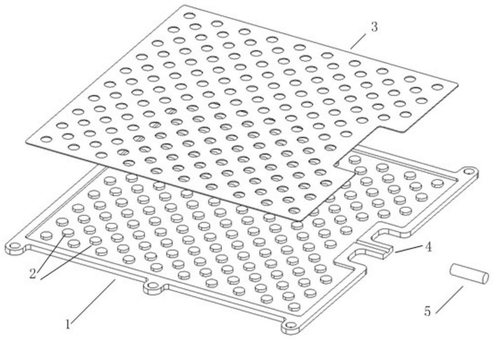
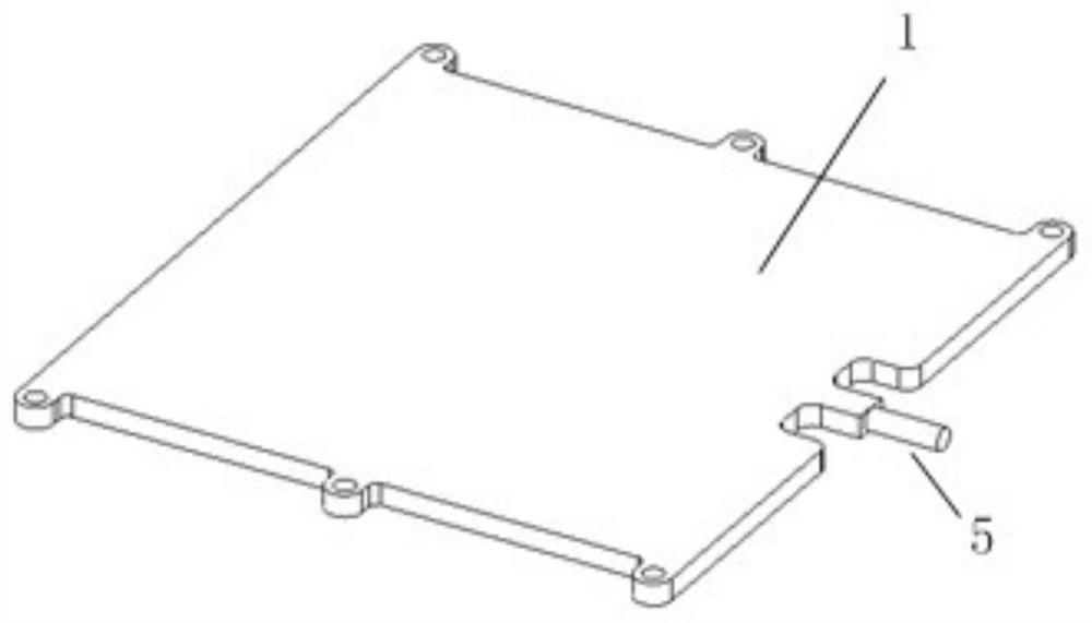
[0043] Such as figure 1 , figure 2 As shown, a flat heat pipe based on a composite structure liquid-absorbing core provided by the present invention includes a base plate 1, a liquid-absorbing core, a liquid filling port 4 and a liquid-filling pipe 5, wherein the base plate 1 includes an upper base plate and a lower base plate, and the liquid-absorbing core It is arranged between the upper base plate and the lower base plate. A liquid filling port 4 is reserved at one end of the base plate 1, and a li...


PUM


Abstract

The invention provides a flat heat pipe based on a liquid absorbing core of a composite structure. The flat heat pipe comprises baseplates, the liquid absorbing core and a liquid filling pipe, whereinthe liquid absorbing core is arranged between the baseplates, and comprises supporting columns and foamed nickel components; the baseplates comprise an upper baseplate and a lower baseplate; the supporting columns are arranged on the upper baseplate and the lower baseplate; the foamed nickel components are matched with the inner wall surface structures of the baseplates; the liquid filling pipe is arranged between the upper baseplate and the lower baseplate; the interior of the flat heat pipe is filled with a working medium through the liquid filling pipe; and a channel where the working medium inside the flat heat pipe flows is jointly defined by the supporting columns and foamed nickel on the foamed nickel components. Through the adoption of the channel where the working medium inside the flat heat pipe flows and which is jointly defined by the supporting columns arranged in an array and the foamed nickel, the resistance to the backflow of the liquid working medium can be reduced when the capillary force is good, the flat heat pipe can achieve the better heat transfer property, and the reliability can be improved during the use of the flat heat pipe.

Description

technical field [0001] The invention relates to the technical field of heat dissipation, in particular to a flat heat pipe based on a liquid-absorbing core of a composite structure, an assembly method, and electronic components. Background technique [0002] With the rapid development of my country's aerospace technology, the detection requirements of spacecraft are developing in the direction of multi-function and multi-target, and the types of payloads that need to be carried have also increased accordingly. However, due to the prioritization of the carrying space of the spacecraft, in order to meet the application requirements, it is necessary to make the load structure smaller and lighter through modular design, and finally process highly integrated electronic equipment. High integration will make the electronic devices inside the device more compact, which will lead to a sharp increase in power density in a small space when the device is running, and the increase in pow...

Claims


Application Information

Patent Timeline
Patent Type & Authority Applications(China)
IPC IPC(8): F28D15/02F28F9/00F28F9/007F28F9/26B23K9/16B23K9/32
CPCB23K9/16B23K9/32F28D15/0233F28F9/001F28F9/0075F28F9/26
Inventor 雷智博董丽宁曹建光郁海勇赵小翔张翔
Owner SHANGHAI SATELLITE ENG INST
Why Eureka
Try Eureka