
Ultrathin vapor chamber, preparation method thereof and electronic equipment

A vapor chamber and ultra-thin technology, applied in lighting and heating equipment, indirect heat exchangers, cooling/ventilation/heating transformation, etc., can solve the problems of increasing manufacturing costs and unfavorable mass production of ultra-thin vapor chambers , to prevent liquid film accumulation, enhance gas-liquid conversion efficiency, and reduce flow resistance

Pending Publication Date: 2022-08-05
INST OF ENGINEERING THERMOPHYSICS - CHINESE ACAD OF SCI
View PDF0 Cites 0 Cited by
  • Summary
  • Abstract
  • Description
  • Claims
  • Application Information

AI Technical Summary

Problems solved by technology

[0003] The traditional single-aperture liquid-absorbent core structure is difficult to meet the design requirements of large capillary force and high permeability at the same time. A large number of scholars have carried out a lot of work on the structural design and optimization of liquid-absorbent cores, such as through homogeneous / heterogeneous Composite wick, double-layer evaporator wick and nano wick technology to improve the heat transfer limit of the vapor chamber
However, overly complex composite structures and nanotechnology are not conducive to the development of ultra-thin vapor chambers, and will increase their manufacturing costs, which is not conducive to mass industrial production of ultra-thin vapor chambers.

Method used


Image

  • Ultrathin vapor chamber, preparation method thereof and electronic equipment
  • Ultrathin vapor chamber, preparation method thereof and electronic equipment
  • Ultrathin vapor chamber, preparation method thereof and electronic equipment

Examples


Embodiment Construction

[0031] In order to make the objectives, technical solutions and advantages of the present disclosure clearer, the present disclosure will be further described in detail below with reference to the specific embodiments and the accompanying drawings. Obviously, the described embodiments are some, but not all, embodiments of the present disclosure. Based on the embodiments in the present disclosure, all other embodiments obtained by those of ordinary skill in the art without creative efforts shall fall within the protection scope of the present disclosure.

[0032] The terminology used herein is for the purpose of describing particular embodiments only and is not intended to limit the present disclosure. The terms "comprising", "comprising" and the like as used herein indicate the presence of stated features, steps, operations and / or components, but do not preclude the presence or addition of one or more other features, steps, operations or components.

[0033] In the present di...


PUM

PropertyMeasurementUnit
thicknessaaaaaaaaaa
thicknessaaaaaaaaaa
porosityaaaaaaaaaa

Abstract

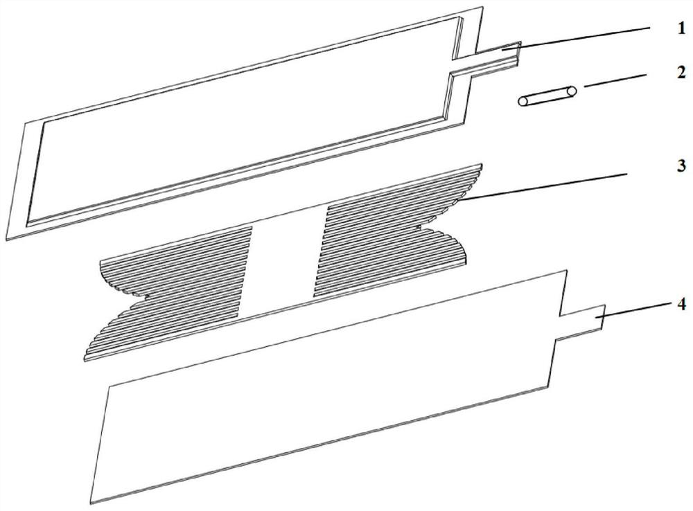
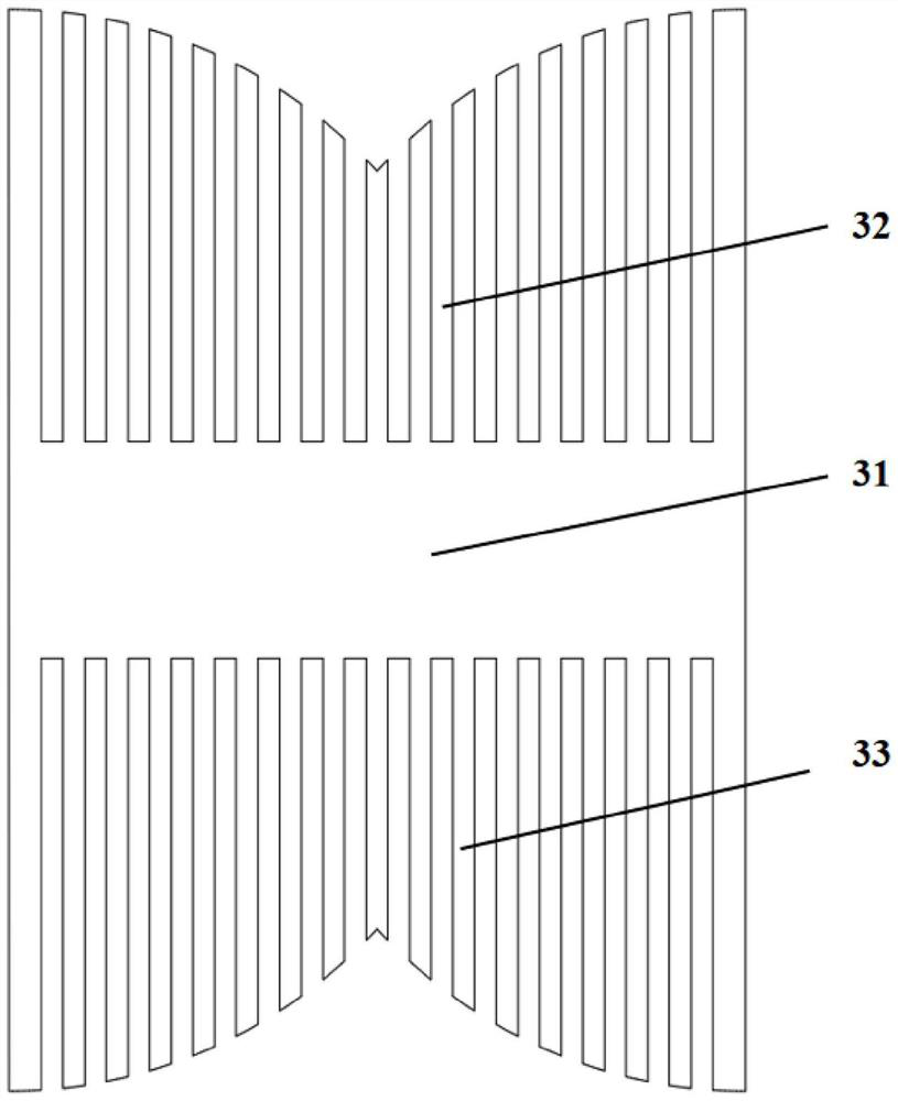
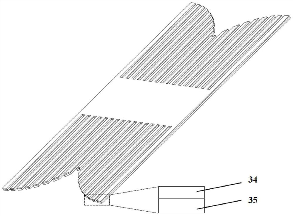
The invention provides an ultrathin vapor chamber which comprises an upper shell plate (1) and a lower shell plate (4), and the periphery of the upper shell plate (1) and the periphery of the lower shell plate (4) are welded to form a closed cavity. The liquid injection pipe (2) is arranged on the closed chamber and is used for vacuumizing the closed chamber and injecting liquid into the closed chamber; the liquid absorption core structure (3) is arranged in the closed cavity, the liquid absorption core structure (3) comprises a central liquid absorption core (31) and a plurality of channel-shaped liquid absorption cores (32) which are distributed on the two sides of the liquid absorption core (31) and are arranged in parallel, the channel-shaped liquid absorption cores (32) form liquid backflow channels, and steam diffusion channels (33) are formed between the adjacent channel-shaped liquid absorption cores (32); the central liquid absorbing core (31) and the channel-shaped liquid absorbing core (32) are respectively composed of a first liquid absorbing core (34) and a second liquid absorbing core (35) which are stacked, the porosity of the liquid absorbing core structure (3) changes in a gradient mode in the direction from the first liquid absorbing core (34) to the second liquid absorbing core (35), and a super-hydrophilic nanometer structure is formed on the surface of the liquid absorbing core structure (3).

Description

technical field [0001] The present disclosure relates to the technical field of vapor chambers, and in particular, to an ultra-thin vapor chamber, a preparation method thereof, and electronic equipment. Background technique [0002] In recent years, portable electronic products have been developing towards high integration and miniaturization. The heat dissipation requirements of electronic chips in confined spaces are getting higher and higher. The development of new efficient heat dissipation technologies is crucial for the development of electronic products. As a phase change heat transfer element, the vapor chamber realizes two-dimensional plane heat transfer. It has the advantages of high heat transfer efficiency, strong temperature uniformity and high reliability. It has been widely used in various heat dissipation fields. However, with the continuous reduction of the thickness of the vapor chamber, especially when the thickness is less than 3mm, the internal vapor dif...

Claims


Application Information

Patent Timeline
Patent Type & Authority Applications(China)
IPC IPC(8): F28D15/04H05K7/20
CPCF28D15/046H05K7/20327H05K7/20336H05K7/20309
Inventor 周峰周敬之周国辉淮秀兰
Owner INST OF ENGINEERING THERMOPHYSICS - CHINESE ACAD OF SCI
Learn More