Supercharge Your Innovation With Domain-Expert AI Agents!

Torsion spring rotating shaft and assembling method

An assembly method and torsion spring technology, which are applied to pivot connections, instruments, electrical and digital data processing, etc., can solve the problems of difficult assembly methods, inability to meet usage requirements, and inconvenient operation, and achieve low assembly difficulty, manpower saving, and operation. handy effect

Pending Publication Date: 2022-04-12
SUZHOU CHENGRUN ELECTRONICS
View PDF0 Cites 0 Cited by
  • Summary
  • Abstract
  • Description
  • Claims
  • Application Information

AI Technical Summary

Problems solved by technology

[0003] At present, the assembly method of the torsion spring shaft is to use the pre-assembly method of the shaft. First, install the angle adjustment gasket into the rotating part, then put the sleeve into the rotating part, install the torsion spring on the sleeve, and install the torsion spring with one foot. For the large rotating plate, the other foot of the torsion spring is rotated by external force and loaded into the groove of the torsion spring gasket. In this installation method, the large rotating plate and the small rotating plate must be locked together with screws, and the working angle of the torsion spring is relatively large. Large, the groove of the torsion spring spacer may be decoupled from one leg of the torsion spring, the assembly method is difficult, the operation is inconvenient, and it cannot meet the actual use needs

Method used


Image

  • Torsion spring rotating shaft and assembling method
  • Torsion spring rotating shaft and assembling method
  • Torsion spring rotating shaft and assembling method

Examples


Embodiment Construction

[0038] The present invention will be further described in detail below in conjunction with the accompanying drawings and specific embodiments. It should be understood that the specific embodiments described here are only used to explain the present invention, but not to limit the present invention.

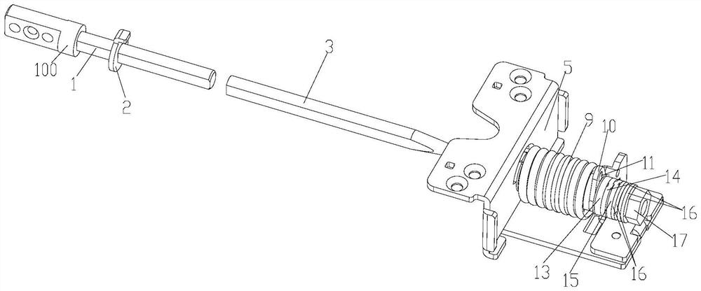
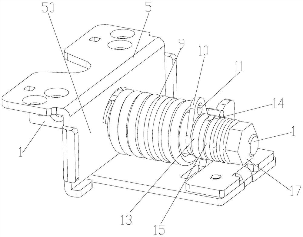
[0039] refer to Figure 1-2 , a torsion spring shaft according to an embodiment of the present invention, including a first support 5, a second support 13, a sleeve 8, a torsion spring washer 10, a torsion spring 9, a temporary assembly 3 and a formal assembly 1 ; The first support 5 has a first pressing surface 50; the second support 13 has a second pressing surface 130 opposite to the first pressing surface 50, and the second support 13 is located on the first support on the seat 5; the sleeve 8 is set between the first pressing surface 50 and the second pressing surface 130; the torsion spring gasket 10 is installed between the sleeve 8 and the second pressing surface 130; the...


PUM


Abstract

The invention discloses a torsion spring rotating shaft and an assembling method, the torsion spring rotating shaft comprises a first support, a second support, a sleeve, a torsion spring gasket, a torsion spring, a temporary assembling part and a formal assembling part, the assembling method of the torsion spring rotating shaft comprises the following steps: the first support and the sleeve penetrate into the temporary assembling part; a torsion spring is installed in the sleeve, one foot of the torsion spring is inserted into the first support, a torsion spring gasket is installed in the temporary assembly part, and then the other foot of the torsion spring is inserted into the torsion spring gasket; the first support is installed in the temporary assembly part, and the second support is locked on the first support; an angle adjusting gasket is installed in the formal assembly part, then the formal assembly part is aligned with the temporary assembly part, and the temporary assembly part is pushed to move forwards till the temporary assembly part is completely ejected out by the formal assembly part; a fastening piece is installed at the tail of the formal assembly piece, and after the fastening piece is adjusted to reach a proper torsion value, assembly of the torsion spring rotating shaft is completed; the torsion spring rotating shaft can be rapidly installed, the assembling difficulty is low, and the production capacity is improved.

Description

technical field [0001] The invention belongs to the technical field of electronic components, and in particular relates to a torsion spring shaft and an assembly method. Background technique [0002] In the prior art, in clamshells or electronic products with rotating parts, such as notebook computers, torsion spring shafts are used to facilitate the opening and closing of the electronic products. [0003] At present, the assembly method of the torsion spring shaft is to use the pre-assembly method of the shaft. First, install the angle adjustment gasket into the rotating part, then put the sleeve into the rotating part, install the torsion spring on the sleeve, and install the torsion spring with one foot. For the large rotating plate, the other foot of the torsion spring is rotated by external force and loaded into the groove of the torsion spring gasket. In this installation method, the large rotating plate and the small rotating plate must be locked together with screws,...

Claims


Application Information

Patent Timeline
IPC IPC(8): F16C11/04G06F1/16
Inventor 崔广权徐进张秀金
Owner SUZHOU CHENGRUN ELECTRONICS
Features
  • R&D
  • Intellectual Property
  • Life Sciences
  • Materials
  • Tech Scout
  • Unparalleled Data Quality
  • Higher Quality Content
  • 60% Fewer Hallucinations
Learn More