Knee structure for crash dummy and adjusting method

A knee and dummy technology, applied in the field of knee structure and adjustment of collision dummies, can solve the problem that the ligament force cannot be adjusted, the response state of the six-degree-of-freedom motion of the human knee cannot be truly reproduced, and the lateral side of the knee cannot be simulated. Ligaments such as the stress method of the anterior cruciate ligament and the posterior cruciate ligament to achieve the effect of improving the effectiveness

Pending Publication Date: 2022-04-12
CHINA AUTOMOTIVE TECH & RES CENT +1
View PDF1 Cites 0 Cited by
  • Summary
  • Abstract
  • Description
  • Claims
  • Application Information

AI Technical Summary

Problems solved by technology

Because the existing pedestrian collision dummy greatly simplifies the knee joint, it can only achieve a single bending degree of freedom and is rigidly connected, and cannot simulate the knee lateral collateral ligament, medial collateral ligament, anterior cruciate ligament and The way the posterior cruciate ligament is stressed, it is impossible to accurately evaluate the collision injury of the vehicle to the pedestrian
In the testing of pedestrian protection regulations in various countries, the throwing leg type (TRL Pedestrian Legforms, aPLILegfom) is mainly used for safety testing. The knee ligaments are replaced by cables. On the one hand, the strength of the ligaments cannot be adjusted, and the overall dummy cannot be realized weight support; on the other hand, this test method of substituting parts for the whole cannot truly reflect the overall impact response of pedestrians.
CN200610011609.4 proposes a four-freedom dummy knee joint mechanism for human body collision protection tests. First, the mechanism cannot truly reproduce the human knee’s six-degree-of-freedom motion response state. Secondly, the mechanism also uses cables to simulate knee ligaments. The leg type also has the technical problems of the above-mentioned throwing leg type test

Method used


Image

  • Knee structure for crash dummy and adjusting method
  • Knee structure for crash dummy and adjusting method
  • Knee structure for crash dummy and adjusting method

Examples


Embodiment Construction

[0030] In order to make the purpose, technical solution and advantages of the present invention clearer, the technical solution of the present invention will be clearly and completely described below. Apparently, the described embodiments are only some of the embodiments of the present invention, but not all of them. Based on the embodiments of the present invention, all other embodiments obtained by persons of ordinary skill in the art without making creative efforts belong to the protection scope of the present invention.

[0031] In the description of the present invention, it should be noted that the terms "center", "upper", "lower", "left", "right", "vertical", "horizontal", "inner", "outer" etc. The indicated orientation or positional relationship is based on the orientation or positional relationship shown in the drawings, and is only for the convenience of describing the present invention and simplifying the description, rather than indicating or implying that the refe...


PUM


Abstract

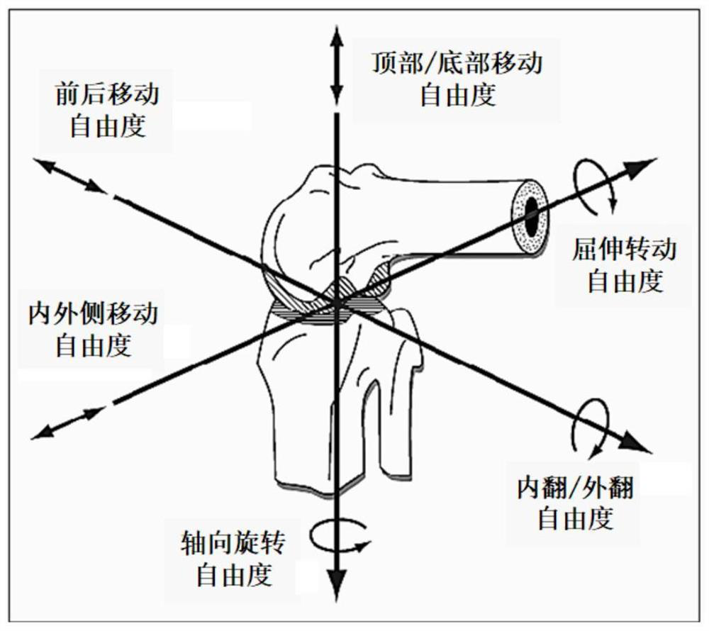
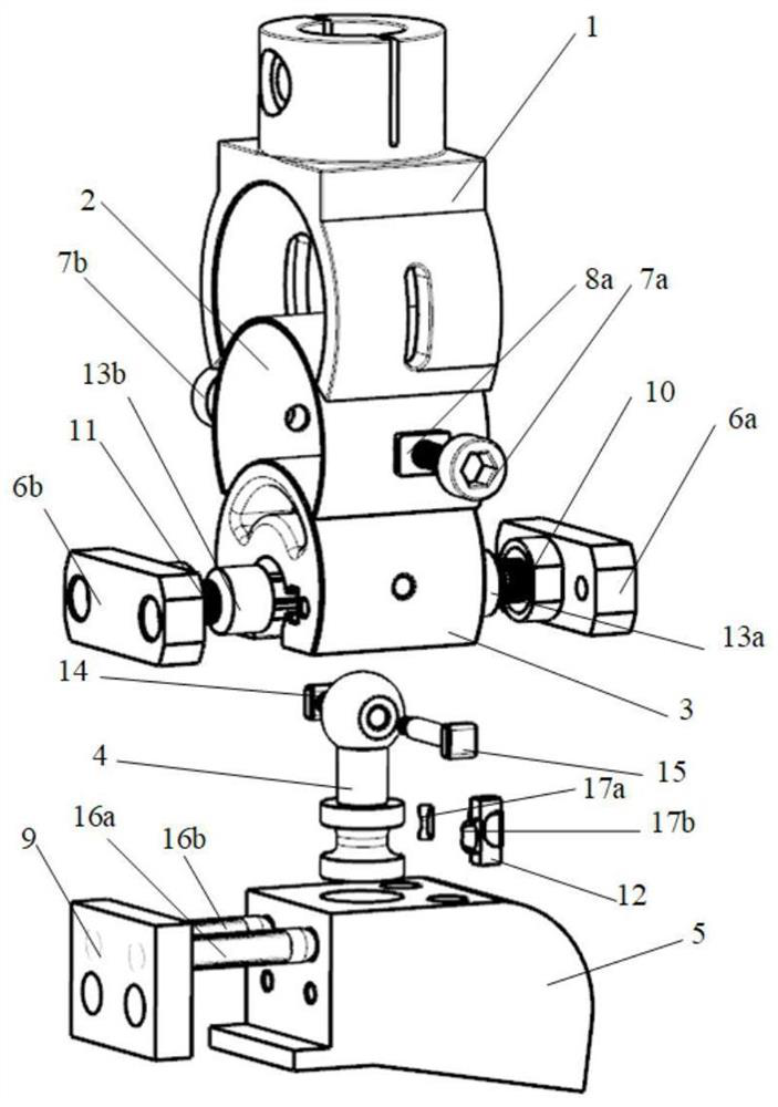
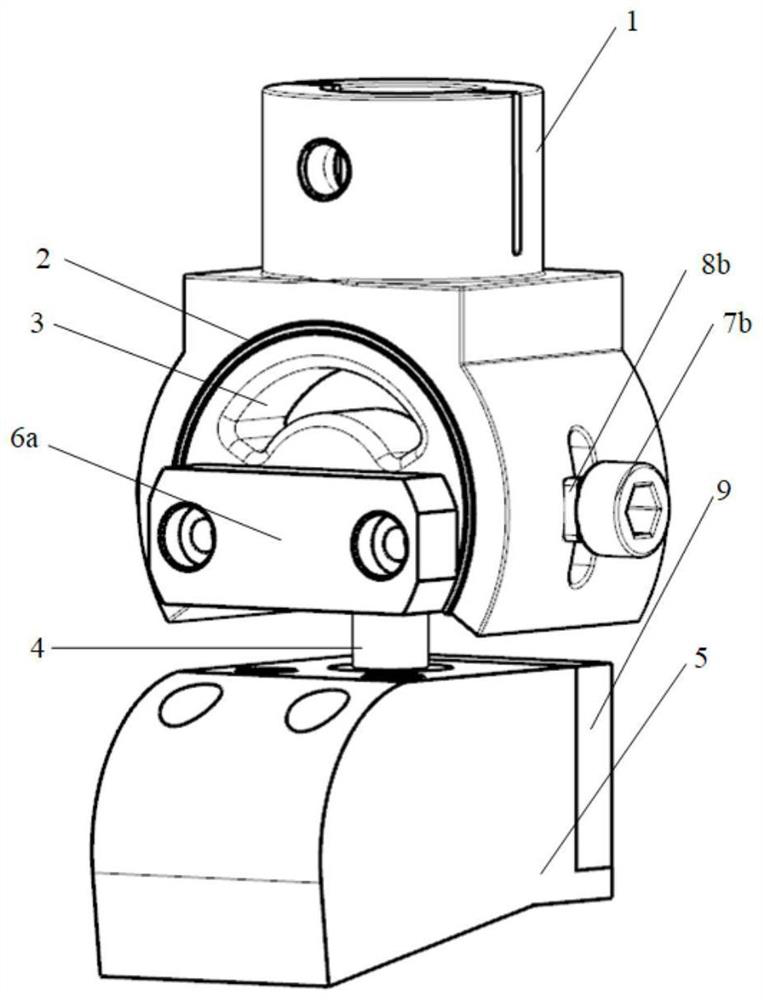
The invention relates to the field of automobile safety collision test dummies, in particular to a knee structure for a collision dummy and an adjusting method. The knee structure comprises an upper leg bone connecting piece, a friction plate, a center connecting block, a connecting rod, a lower leg bone connecting piece and a cover plate, the upper leg bone connecting piece can rotate around the friction plate and the center connecting block and move up and down, and the center connecting block is provided with a first ball sleeve, a first elastic piece, a first pressing plate, a second ball sleeve, a second elastic piece and a second pressing plate; the top end of the connecting rod is arranged in the center connecting block and connected with the first ball sleeve and the second ball sleeve. A first limiting piece is further arranged at the top end of the connecting rod, and the top end of the connecting rod can rotate around the first limiting piece. The knee structure can reproduce all degrees of freedom of the knee joint of a human body, can reflect the stress mode of the knee in the collision process, more accurately evaluates the collision injury of a vehicle to a pedestrian, and improves the effectiveness of a collision test.

Description

technical field [0001] The invention relates to the field of automobile safety collision test dummy, in particular to a knee structure and adjustment method for a collision dummy. Background technique [0002] As the number of cars in our country increases year by year, traffic accidents also increase sharply. Traffic accidents in which pedestrians and vehicles collide directly account for a large proportion of them. In such forms of traffic accidents, the knee is often the part of the human body that suffers the most damage. At the same time, the knee joint is the most complicated joint in the human body. Its treatment and rehabilitation The process is lengthy and expensive. [0003] In order to improve the safety of automobiles against pedestrian collisions, special-purpose pedestrian standing posture collision dummy is now used for relevant collision tests, and the degree of damage caused by vehicles to pedestrians' lower limbs is evaluated through tests through tests. ...

Claims


Application Information

Patent Timeline
IPC IPC(8): G01M17/007G01M7/08
Inventor 马伟杰刘志新陈弘刘伟东王凯解明浩郝烨乔胜华
Owner CHINA AUTOMOTIVE TECH & RES CENT
Why Eureka
Try Eureka