Adjustment of scanning performance of lidar sensor

A lidar and sensor technology, applied in the field of scanning motion, can solve the problems of detector saturation, image floating, the number of false detections, etc., and achieve the effect of improving the phase jitter tolerance

Pending Publication Date: 2022-04-12
ROBERT BOSCH GMBH
View PDF0 Cites 0 Cited by
  • Summary
  • Abstract
  • Description
  • Claims
  • Application Information

AI Technical Summary

Problems solved by technology

This problem arises, for example, in the case of identically constructed or technologically similar lidar sensors and can lead to an increased number of false detections or to sensor saturation or image blooming (blooming)

Method used


Image

  • Adjustment of scanning performance of lidar sensor
  • Adjustment of scanning performance of lidar sensor
  • Adjustment of scanning performance of lidar sensor

Examples


Embodiment Construction

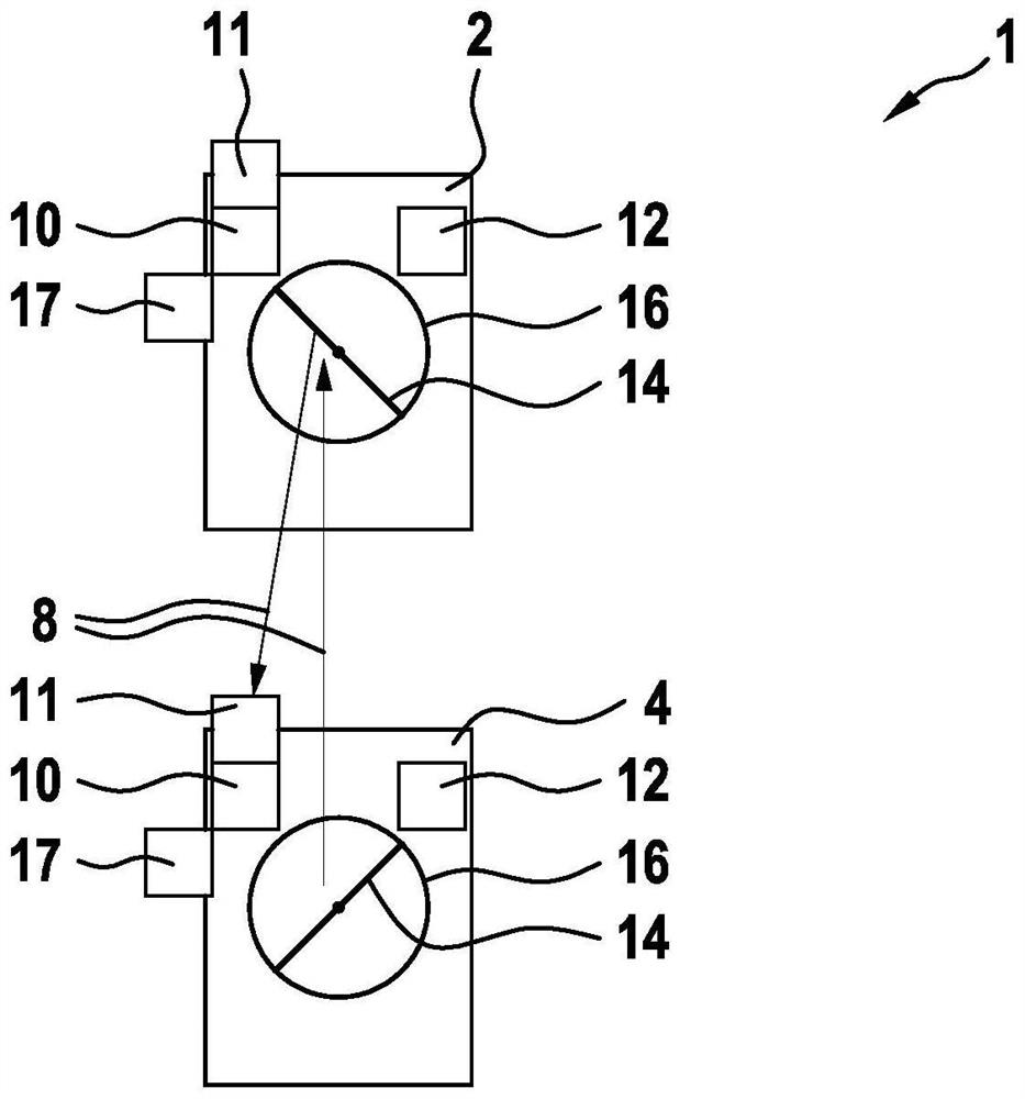
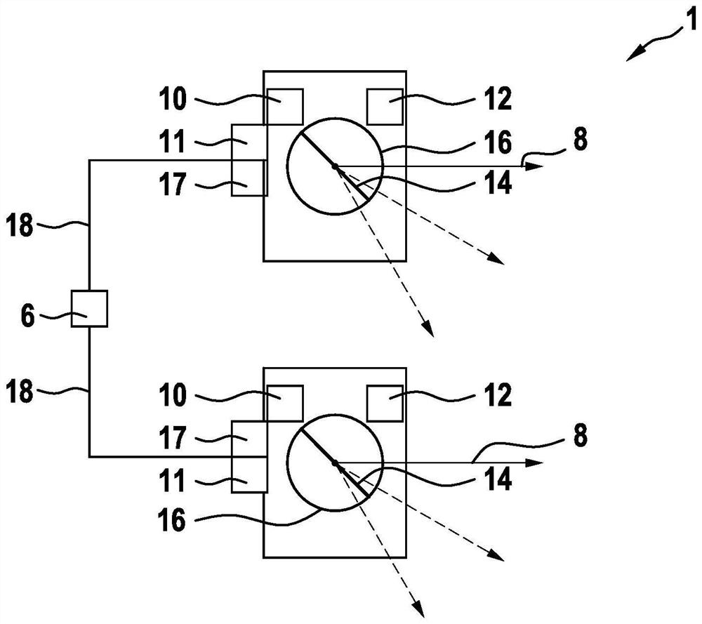
[0034] figure 1 with figure 2 A schematic top view of an arrangement 1 with two interfering lidar sensors 2 , 4 is shown in order to carry out a method for setting the scanning behavior of at least one lidar sensor 2 , 4 via a control device 6 . here, figure 1A schematic plan view of an arrangement 1 with two interfering lidar sensors 2 , 4 is shown.

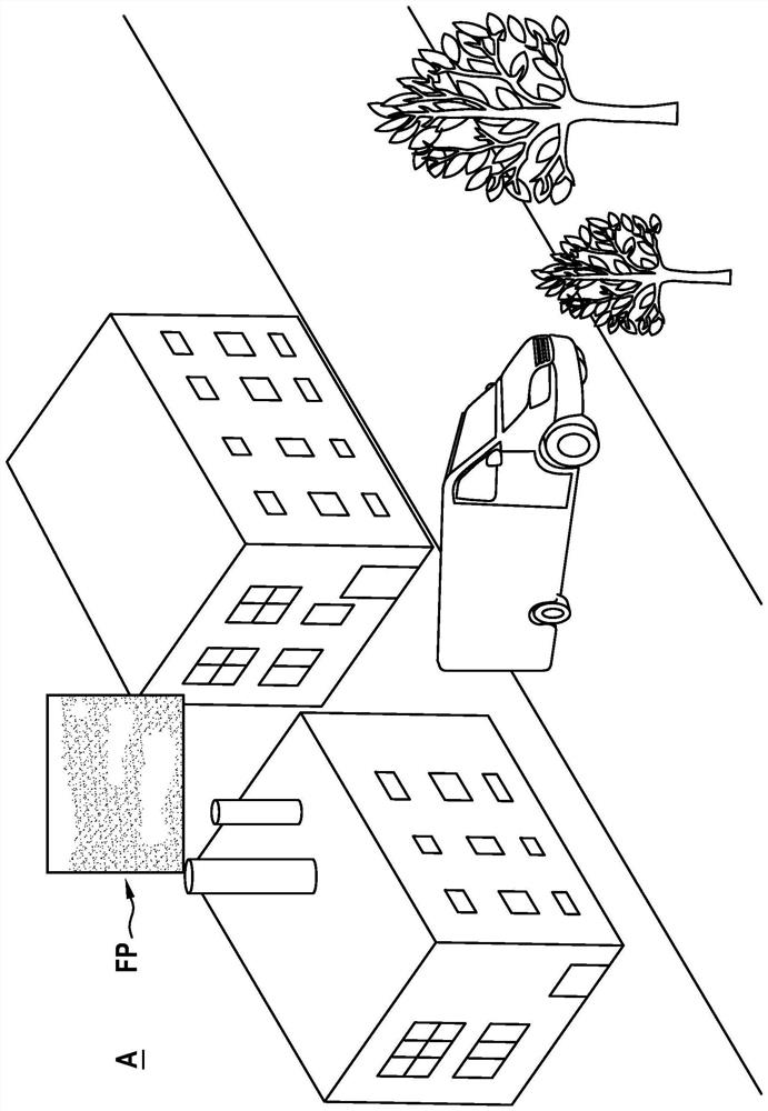
[0035] image 3 A schematic 3D point cloud is shown to illustrate the influence of two mutually obstructing lidar sensors 2 , 4 . In this case, an overshooting of the receiving unit 12 of the lidar sensor 2 , 4 can be detected, in particular by means of a false positive measurement FP in an open area or in an area of ​​the scan area A that is generally free of buildings. This overshoot is caused by receiving the resulting beam 8 of an adjacent source.

[0036] A beam of radiation 8 generated by the lidar sensor 2 , 4 is emitted in the scanning range. Lidar sensors 2 , 4 are designed as structurally identical or technical...


PUM


Abstract

The invention relates to a method for adjusting the scanning performance of at least one lidar sensor by means of a control device, in which measurement data of the lidar sensor are received and at least one parameter is ascertained, and the scanning performance of the lidar sensor is adjusted on the basis of the ascertained parameter or in a time-dependent manner. In addition, the invention also discloses a control device.

Description

technical field [0001] The invention relates to a method for setting a scanning movement of at least one lidar sensor by a control device. Furthermore, the invention relates to a control device. Background technique [0002] In order to implement various driver assistance functions and automated driving functions, LiDAR sensors are used in the vehicle area. Scanning or rotating lidar sensors are usually used, which scan the scanning field with the aid of a collimated laser beam. [0003] In particular, lidar sensors configured as rotary macroscanners are able to detect large horizontal scanning areas. Here, a part of the lidar sensor is arranged on the rotor and is rotated or pivoted to scan the scanning area. For example, both the transmitting unit and the receiving unit of the lidar sensor can be arranged on the rotor. Alternatively, depending on the configuration of the lidar sensor, it is possible for the beam deflection structure to be arranged on the rotor via mirr...

Claims


Application Information

Patent Timeline
Patent Type & Authority Applications(China)
IPC IPC(8): G01S7/497
CPCG01S7/4817G01S17/931G01S7/497G01S17/87
Inventor M·卡米尔R·哈斯
Owner ROBERT BOSCH GMBH
Why Eureka
Try Eureka