
Driving control circuit of lifting socket and lifting socket

A technology for driving control circuits and sockets. It is applied in the direction of AC motor control, circuits, and control systems. It can solve problems such as low sensitivity of sockets, high peak value of motor voltage, and noise interference, so as to reduce noise interference and ensure accuracy.

Pending Publication Date: 2022-04-12
厦门芯阳科技股份有限公司
View PDF0 Cites 0 Cited by
  • Summary
  • Abstract
  • Description
  • Claims
  • Application Information

AI Technical Summary

Problems solved by technology

The current lifting socket generally adopts a full-bridge drive circuit composed of 4 NMOS tubes / transistors in circuit design, and needs 4 ports to drive 4 NMOS tubes / transistors respectively, so as to control the operation of the motor. In this way, The circuit design is quite complicated, the production cost is high, and the sensitivity of controlling the motor to drive the socket up and down is low
In addition, the peak value of the voltage at both ends of the motor is too high, causing noise interference, which cannot guarantee precise control of the operation of the motor
[0003] In addition, in daily life, foreign objects are often mixed in the process of using the lifting socket. For example, when the socket is descending, because there are plugs, chargers, USB charging cables and other objects inserted on the socket panel, the socket will be blocked for storage. , and will damage plugs, chargers, USB charging cables and other objects; or, there are no plugs and other objects on the socket panel, but when the socket is lowered close to the table, foreign objects such as electric wires and hands are accidentally leaned against the socket between the table and the table, there is a risk of pinching

Method used


Image

  • Driving control circuit of lifting socket and lifting socket
  • Driving control circuit of lifting socket and lifting socket

Examples


Embodiment Construction

[0025] In order to make the purpose, technical solutions and advantages of the embodiments of the present invention clearer, the technical solutions in the embodiments of the present invention will be clearly and completely described below in conjunction with the drawings in the embodiments of the present invention. Obviously, the described embodiments It is a part of the embodiments of the present invention, rather than all embodiments; the technical features designed in the different embodiments of the present invention described below can be combined as long as they do not constitute conflicts; based on the embodiments of the present invention, the present invention All other embodiments obtained by persons of ordinary skill in the art without creative efforts fall within the protection scope of the present invention.

[0026] In describing the present invention, it should be understood that the terms "central", "lateral", "upper", "lower", "left", "right", "vertical", "hori...


PUM


Abstract

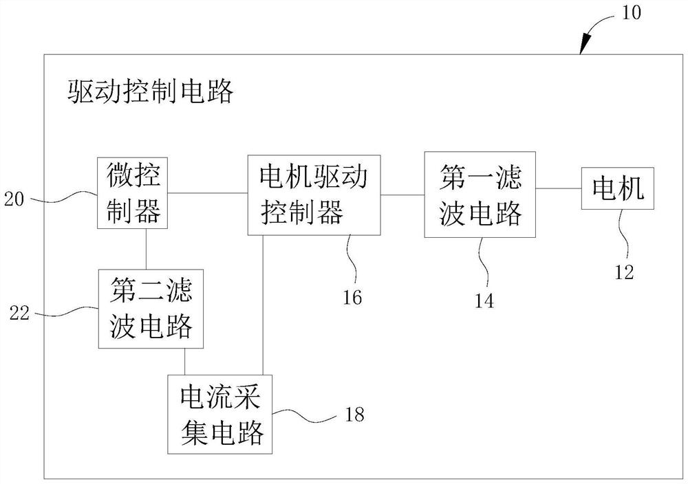
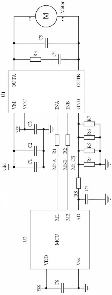
The invention provides a driving control circuit of a lifting socket and the lifting socket. The driving control circuit comprises a motor, a first filter circuit, a motor driving controller, a current acquisition circuit and a microcontroller. The first filter circuit is coupled with the motor; the motor driving controller is coupled with the first filter circuit and drives the motor through the first filter circuit; the current acquisition circuit is coupled with the motor driving controller and is used for acquiring the working current of the motor; the microcontroller is coupled with the motor driving controller and is provided with a first control port M1, a second control port M2 and an acquisition port AD, the microcontroller controls the motor driving controller through the first control port M1 and the second control port M2, and the acquisition port AD is coupled with the current acquisition circuit. By means of the arrangement, operation of the motor can be controlled more accurately so as to control movement of the lifting socket, and the production cost is low; in addition, an anti-pinch protection mechanism can be formed to prevent the lifting socket from pinching foreign matters.

Description

technical field [0001] The invention relates to the technical field of sockets, in particular to a driving control circuit of a lifting socket and a lifting socket. Background technique [0002] In household and commercial appliances, some components are often set to control them to realize simple movements for more convenient use, such as electric control sockets that can be raised and lowered. The current lifting socket generally adopts a full-bridge drive circuit composed of 4 NMOS tubes / transistors in circuit design, and needs 4 ports to drive 4 NMOS tubes / transistors respectively, so as to control the operation of the motor. In this way, The circuit design is quite complicated, the production cost is high, and the sensitivity of controlling the motor to drive the socket up and down is low. In addition, the peak value of the voltage at both ends of the motor is too high, causing noise interference, which cannot ensure precise control of the operation of the motor. [0...

Claims


Application Information

Patent Timeline
Patent Type & Authority Applications(China)
IPC IPC(8): H02P25/16H02H7/085H02H9/02H01R13/66H01R13/719
Inventor 黄小岩马福长王志勇刘双春魏肃
Owner 厦门芯阳科技股份有限公司
Learn More