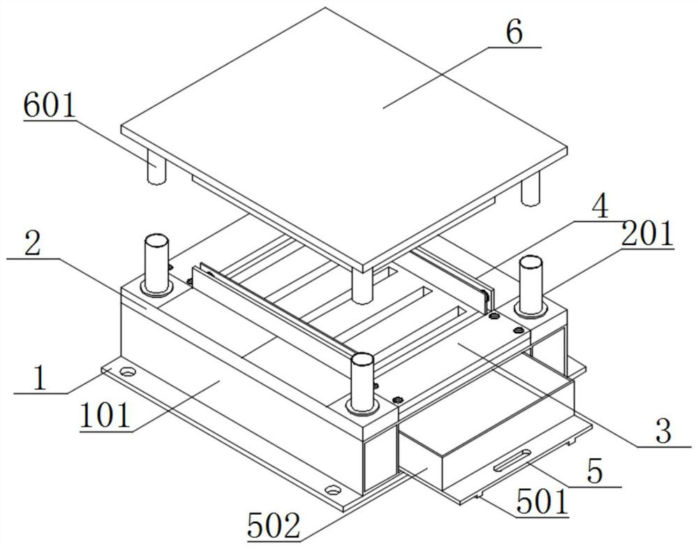
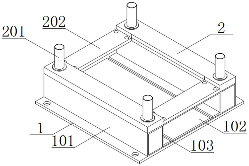
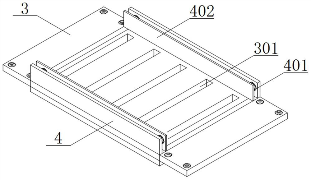
Blanking structure

A blanking and mold base technology, applied in storage devices, metal processing equipment, feeding devices, etc., can solve the problems of inconvenient use by staff, inconvenient waste collection, inconvenient waste disposal, etc., to achieve convenient processing and improve work efficiency , to ensure the effect of stability

Pending Publication Date: 2022-04-26
WUXI MICRO RES
View PDF6 Cites 0 Cited by
  • Summary
  • Abstract
  • Description
  • Claims
  • Application Information

AI Technical Summary

Problems solved by technology

However, when in use, it is mostly inconvenient for the staff to collect the fallen waste materials, it is not convenient for the staff to carry out subsequent processing on the waste materials, and it is inconvenient for the staff to use

Method used


Image

  • Blanking structure
  • Blanking structure
  • Blanking structure

Examples


Embodiment Construction

[0024] In the description of this application, it should be noted that the terms "upper", "lower", "inner", "outer", "front end", "rear end", "both ends", "one end", "another end" The orientation or positional relationship indicated by etc. is based on the orientation or positional relationship shown in the drawings, which is only for the convenience of describing the application and simplifying the description, rather than indicating or implying that the referred device or element must have a specific orientation, use a specific Azimuth configuration and operation, therefore, should not be construed as limiting the application. In addition, the terms "first" and "second" are used for descriptive purposes only, and should not be understood as indicating or implying relative importance.

[0025] In the description of this application, it should be noted that, unless otherwise clearly specified and limited, the terms "installed", "set with", "connected", etc. should be understoo...


PUM


Abstract

The blanking structure comprises a bottom plate, a base is mounted at the top of the bottom plate, and a collecting groove is formed in the inner side of the base; the lower die base is mounted at the top of the base, and a mounting groove is formed in the top of the lower die base; the female die is fixed on the inner side of the mounting groove through a bolt; the supporting plate is mounted at the top of the female die; the mounting plate is movably mounted on the inner side of the collecting tank; and the upper die holder is mounted at the top of the lower die holder in an embedded manner.

Description

technical field [0001] The present application relates to the technical field of molds, for example, to a blanking structure. Background technique [0002] A mold is a tool used to make shaped objects. This tool is composed of a variety of parts, and different molds are composed of different parts. It mainly realizes the processing of the shape of the article through the change of the physical state of the formed material, but when the air-conditioning fin blanking mold in the related art is in use, it is mostly inconvenient for the staff to collect the fallen waste, and it is not convenient for the staff to collect the waste. Follow-up processing is not convenient for staff to use. [0003] A special blanking die structure is disclosed in the related art, which includes a lower mold base, a lower backing plate, a lower formwork, an upper splint, an upper backing plate and an impact plate, and a lower backing plate is fixedly installed on the top of the lower mold base. Ho...

Claims


Application Information

Patent Timeline
Patent Type & Authority Applications(China)
IPC IPC(8): B21D43/20
CPCB21D43/20
Inventor 蒋文红虞泽成叶民生朱其红
Owner WUXI MICRO RES
Why Eureka
Try Eureka