Cutting tool

A cutting tool and tool body technology, which is applied in the field of tool design and manufacturing, can solve problems such as force deformation of the positioning surface, and achieve the effect of stably clamping the blade and reducing inclination

Active Publication Date: 2022-04-29
XIAMEN GOLDEN EGRET SPECIAL ALLOY
View PDF11 Cites 0 Cited by
  • Summary
  • Abstract
  • Description
  • Claims
  • Application Information

AI Technical Summary

Problems solved by technology

[0006] The purpose of the present invention is to overcome the deficiencies of the prior art and provide a cutting tool. Through structural improvement, the cutting tool in the prior art can solve the problems of high-feed cutting, grooving, and transverse turning and profiling with relatively large depth of cut. When the positioning surface is stressed and deformed, there is a gap in the clamping. Due to the small blade width, the blade has insufficient rigidity when restraining the lateral displacement and the blade torsion caused by the inclination of the positioning surface. It can ensure stable clamping of the blade and reduce the Characteristics of the risk of tilting, breaking and chipping during insert machining

Method used


Image

  • Cutting tool
  • Cutting tool
  • Cutting tool

Examples


Embodiment

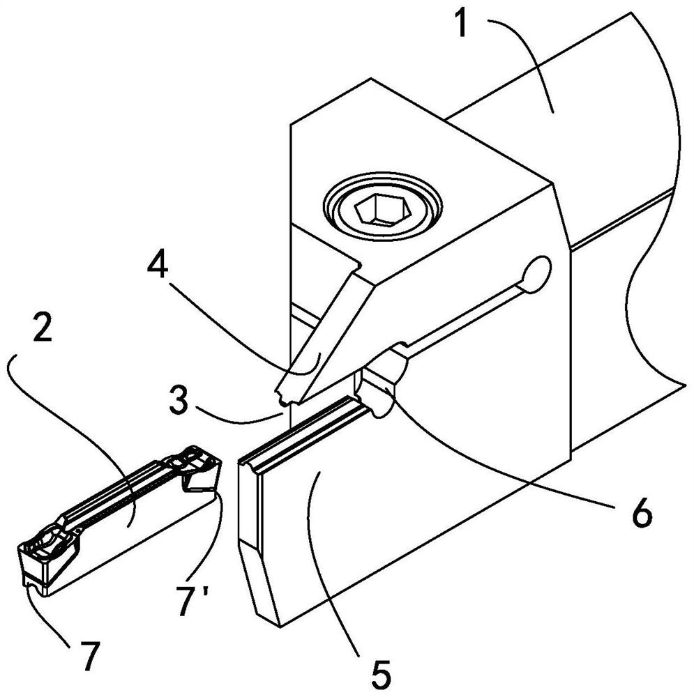
[0030] see Figure 1 to Figure 8 As shown, a cutting tool of the present invention includes a cutter body 1 made of a first material and a blade 2 made of a second material that is harder than the first material; wherein, the cutter body is made The first material of 1 can be steel, including various alloy steels, spring steel, etc.; the second material of blade 2 can be hard alloy or cermet.

[0031] see figure 1As shown, the front end of the cutter body 1 is provided with a groove 3 for clamping the blade 2, the groove 3 is composed of an upper elastic clamping arm 4, a lower rigid clamping part 5 and a rear positioning surface 6, and Through mechanical clamping, the cutter body 1 clamps the blade 2 from the up and down direction; the blade 2 is installed in the groove 3 of the cutter body 1, and the bottom of the blade 2 is supported by the lower rigid clamping part 5 of the cutter body 1 , the top of the blade 2 is pressed and clamped by the upper elastic clamping arm 4;...


PUM


Abstract

The invention discloses a cutting tool. The cutting tool comprises a tool body and a blade, the cutter body is provided with a groove, and the groove is composed of an upper elastic clamping arm, a lower rigid clamping part and a rear positioning face. At least one clamping surface of the cutter body is viewed towards the cross section direction of the opening of the groove of the cutter body; the two first contact surfaces form a preset obtuse angle gamma, the first large arc surface is connected between the inner sides of the two first contact surfaces, the two first inclined surfaces are connected to the outer sides of the two first contact surfaces respectively, and the two first platforms are connected to the outer sides of the two first inclined surfaces respectively; the blade is provided with a corresponding matching structure; and when the blade is arranged in the cutter body and clamped, the two first contact surfaces of the cutter body are correspondingly contacted with the two second contact surfaces of the blade. The blade clamping device has the beneficial effects that it can be guaranteed that the blade is stably clamped, and the risks of inclination, fracture and tipping generated in the blade machining process are reduced.

Description

technical field [0001] The invention relates to the technical field of cutting tool design and manufacture, in particular to a cutting tool mainly used in cutting and grooving, turning and profiling. Background technique [0002] Cutting and grooving, turning and profiling processing tools mainly include grooving and cutting processing based on radial feed and turning and profiling processing based on axial feed. The cutting tools and cutting inserts used for cutting are usually small in width and are subjected to multi-directional cutting forces during processing. When the machine tool feeds, the cutting force of the workpiece and the blade is transmitted to the clamping and positioning surface between the blade and the cutter body through the tool tip, and the positioning method of the clamping and positioning surface has a significant impact on the cutting process of the cutting tool. [0003] When the cutting tool performs turning and profiling with the feed mainly in t...

Claims


Application Information

Patent Timeline
Patent Type & Authority Applications(China)
IPC IPC(8): B23B27/00B23B27/16
CPCB23B27/00B23B27/1603B23B2200/28
Inventor 王杰伟施永鑫周鋆林伟鑫张硕
Owner XIAMEN GOLDEN EGRET SPECIAL ALLOY
Why Eureka
Try Eureka