Unlock instant, AI-driven research and patent intelligence for your innovation.

System and method for automatically identifying distance between steel bars to achieve straightening and deviation rectifying

A technology of steel bar spacing and automatic identification, applied in the field of steel bar binding, can solve the problems that the robot cannot continue to walk, and the position of the steel bar cannot be adjusted.

Pending Publication Date: 2022-04-29
CHINA CONSTR EIGHT ENG DIV CORP LTD +1
View PDF2 Cites 0 Cited by
  • Summary
  • Abstract
  • Description
  • Claims
  • Application Information

AI Technical Summary

Problems solved by technology

[0005] The purpose of the present invention is to overcome the defects of the prior art, to provide a system and method for automatically identifying the spacing of steel bars to achieve straightening and deviation correction, and to solve the problem that the existing steel bar binding robot cannot adjust the position deviation of the steel bar, and the position of the steel bar is offset Sometimes it is easy to cause the robot to be unable to continue walking and require manual intervention to adjust

Method used


Image

  • System and method for automatically identifying distance between steel bars to achieve straightening and deviation rectifying
  • System and method for automatically identifying distance between steel bars to achieve straightening and deviation rectifying
  • System and method for automatically identifying distance between steel bars to achieve straightening and deviation rectifying

Examples


Embodiment Construction

[0038] The present invention will be further described below in conjunction with the accompanying drawings and specific embodiments.

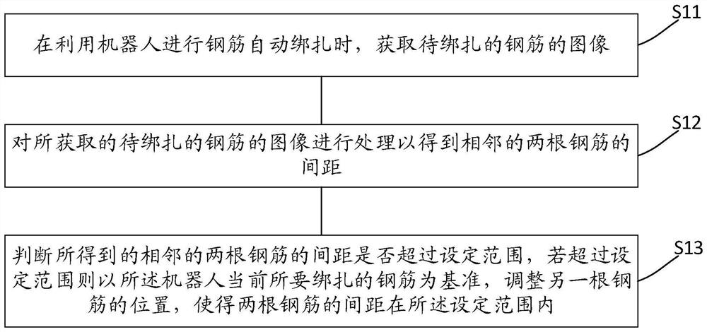
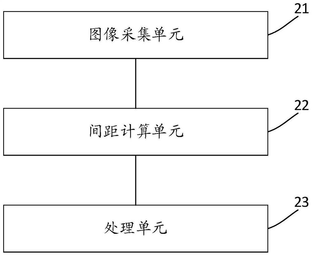
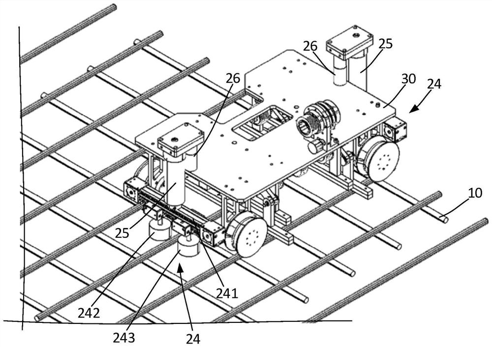
[0039] refer to figure 1 , the present invention provides a system and method for automatically identifying the spacing of steel bars to achieve straightening and deviation correction, which can provide the functions of steel bar straightening and deviation correction for automatic steel bar binding robots, and can automatically correct deviations of steel bars when it is found that the steel bars are offset , to ensure that the location of the steel bars is accurate, on the one hand, it can ensure the binding quality of the steel bars, on the other hand, it can ensure that the robot can walk along the steel bars smoothly, avoiding the robot's inability to walk due to the deviation of the steel bars, and without manual intervention, the whole process is fully automated. It has high practical use value. The system and method for automatically i...


PUM


Abstract

The invention relates to a system and method for automatically recognizing the distance between steel bars to achieve straightening and deviation rectification, and the method comprises the following steps: obtaining an image of a to-be-bound steel bar when a robot is used for carrying out the automatic binding of the steel bar; the obtained images of the reinforcing steel bars to be bound are processed to obtain the distance between every two adjacent reinforcing steel bars; and whether the obtained distance between the two adjacent steel bars exceeds a set range or not is judged, and if the distance between the two adjacent steel bars exceeds the set range, the position of the other steel bar is adjusted with the steel bar to be bound by the robot as the reference, so that the distance between the two steel bars is within the set range. The positions of the reinforcing steel bars are automatically adjusted when the distance between the reinforcing steel bars exceeds the set range, straightening and deviation rectifying of the reinforcing steel bars are achieved, it is ensured that the robot can walk along the reinforcing steel bars, manual intervention is not needed, and the problem that the robot cannot walk due to deviation of the reinforcing steel bars is effectively solved.

Description

technical field [0001] The invention relates to the technical field of steel bar binding, in particular to a system and method for automatically identifying the distance between steel bars to realize straightening and deviation correction. Background technique [0002] At present, on-site steel bar binding on construction sites is still in the manual stage. Manual identification of binding points and manual binding of steel bars are prone to problems such as missed binding and broken binding wires, which consume a lot of manpower and material resources. As a result, there are fewer and fewer construction workers, so the use of automation is the way to solve the shortage of on-site construction manpower in the future. [0003] With the popularization of automation technology, more and more automatic binding tools have been produced. For example, Chinese patent CN111576885A proposes a steel binding robot intelligent binding construction method, which uses laser scanning to est...

Claims


Application Information

Patent Timeline
Patent Type & Authority Applications(China)
IPC IPC(8): G06T7/00G06T7/73E04G21/12
CPCG06T7/0004G06T7/73E04G21/12G06T2207/10028
Inventor 王明绅王鹏飞刘世涛韩立芳黄青隆杨燕
Owner CHINA CONSTR EIGHT ENG DIV CORP LTD