Flexible joint jitter suppression method and system based on trajectory optimization control

A flexible joint and trajectory optimization technology, applied in the direction of program control manipulators, manufacturing tools, manipulators, etc., can solve problems such as equipment running lag, residual jitter, end jitter, etc., and achieve the effect of improving operating efficiency, improving residual jitter, and acceleration optimization.

Active Publication Date: 2022-05-06
智昌科技集团股份有限公司
View PDF9 Cites 0 Cited by
  • Summary
  • Abstract
  • Description
  • Claims
  • Application Information

AI Technical Summary

Problems solved by technology

The traditional trajectory shaping method will cause the problem of running lag, which is caused by the lag after the ZV (ZVD) shaper processes the trajectory. The lag time depends on the number of pulses for convolution and the time of pulse application. When the number The more, the more serious the hysteresis, the greater the time interval of pulse application, the more serious the hysteresis
However, in practical engineering applications, high production efficiency is necessary, so the equipment operation lag caused by the traditional input shaper is unacceptable
[0004] The flexible joints of tandem robots often lead to serious end-jitter problems. If each joint is flexible, the accumulation of flexibility will lead to severe end-jitter and residual shake after stopping. The shake problem needs to be solved urgently;
[0005] The traditional trajectory shaping method is easy to lead to the phenomenon of running time delay, especially for point-to-point operation. If there is a delay in each trajectory, it will not be able to achieve efficient operation in the end.

Method used


Image

  • Flexible joint jitter suppression method and system based on trajectory optimization control
  • Flexible joint jitter suppression method and system based on trajectory optimization control
  • Flexible joint jitter suppression method and system based on trajectory optimization control

Examples


Embodiment Construction

[0058] The method for suppressing vibration of a flexible joint based on trajectory optimization control and the technical solution of the system of the present invention will be further described in detail in conjunction with embodiments below.

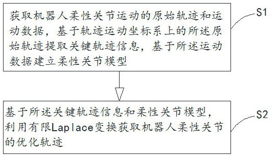
[0059] Such as figure 1 As shown, the method for suppressing vibration of flexible joints based on trajectory optimization control in this embodiment includes: S1~S2

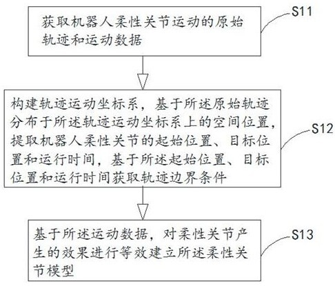
[0060]S1. Obtain the original trajectory and motion data of the flexible joint motion of the robot, extract key trajectory information based on the original trajectory on the trajectory motion coordinate system, and establish a flexible joint model based on the motion data;

[0061] S2. Based on the key trajectory information and the flexible joint model, use finite Laplace transformation to obtain an optimized trajectory of the flexible joint of the robot.

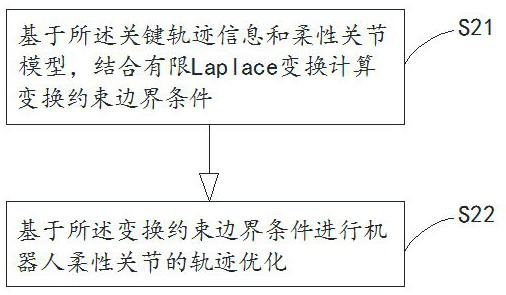
[0062] further, such as figure 2 As shown, based on the key trajectory information and the flexible joint mo...


PUM


Abstract

The invention relates to the technical field of flexible joint jitter suppression, discloses a flexible joint jitter suppression method and system based on trajectory optimization control, and provides a jitter suppression method based on trajectory optimization, and belongs to the field of active control. According to the finite Laplace trajectory optimization method for trajectory design based on key trajectory information and in combination with a flexible joint model, the key trajectory information is a starting position, a target position and running time used for running from the starting position to the target position, and compared with traditional input shaping, the problem of running delay does not exist; according to the method, the finite Laplace trajectory optimization method is performed based on the initial position, the target position and the running time required for reaching the target position, so that acceleration optimization can be realized, residual jitter of the flexible joint of the robot is improved, and the running stability is improved.

Description

technical field [0001] The invention relates to the technical field of vibration suppression of flexible joints, in particular to a vibration suppression method and system for flexible joints based on trajectory optimization control. Background technique [0002] The flexibility in the robot is mainly divided into the flexibility of the connecting rod and the flexibility of the joint. Due to the existence of the flexibility, the robot will have process jitter and residual jitter after stopping. In order to improve the control performance, the jitter suppression method for these two kinds of flexibility mainly Divided into active suppression method and passive suppression method two categories. Since the purpose of passive suppression is to optimize the design of the structure of the flexible robot by selecting various energy-consuming or energy-storage materials to achieve the purpose of reducing vibration, this application does not consider passive suppression for the time ...

Claims


Application Information

Patent Timeline
Patent Type & Authority Applications(China)
IPC IPC(8): B25J9/16
CPCB25J9/1664B25J9/1661B25J9/1612B25J9/163
Inventor 甘中学黄尧谢云斌
Owner 智昌科技集团股份有限公司
Why Eureka
Try Eureka