Sliding cam system with sliding slots and stops

A cam system, sliding technology, applied in the direction of engine components, machines/engines, mechanical equipment, etc., can solve the problems of shaft damage, large transformation force load, proportionally larger tolerance chain, etc.

Inactive Publication Date: 2016-01-13
SCHAEFFLER TECH AG & CO KG
View PDF8 Cites 0 Cited by
  • Summary
  • Abstract
  • Description
  • Claims
  • Application Information

AI Technical Summary

Problems solved by technology

[0003] The shaft is weakened in all areas of the sliding cam due to drilling, causing non-negligible damage to the shaft, which is loaded by a large shifting force
[0004] Furthermore, the problem that arises in sliding cam systems of this type is that the tolerance chain between the actuator or the actuating pin and the slide groove becomes proportionally larger

Method used


Image

  • Sliding cam system with sliding slots and stops
  • Sliding cam system with sliding slots and stops
  • Sliding cam system with sliding slots and stops

Examples


Embodiment Construction

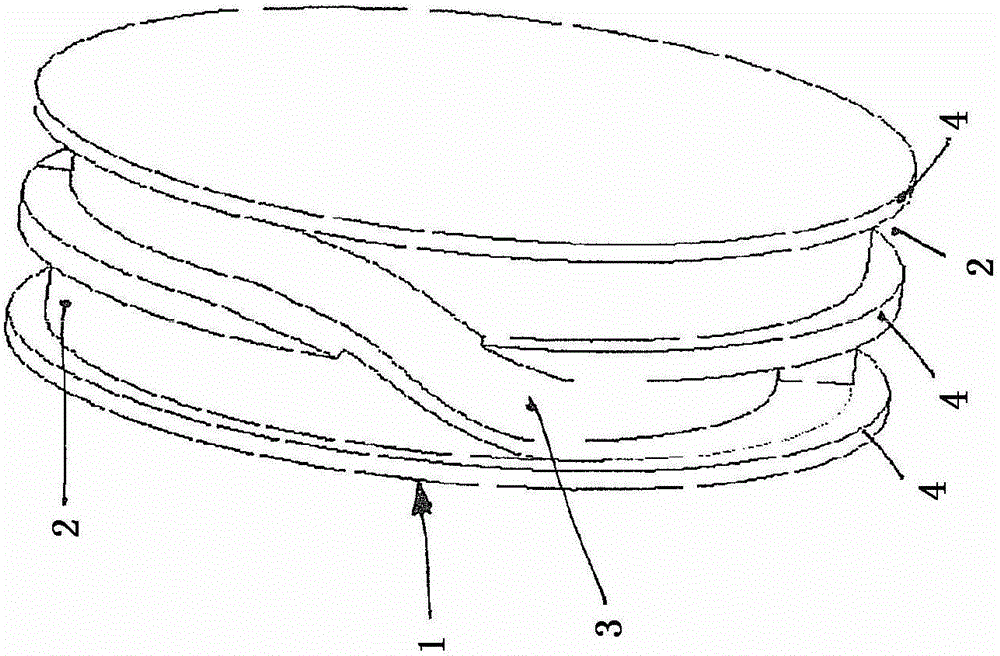
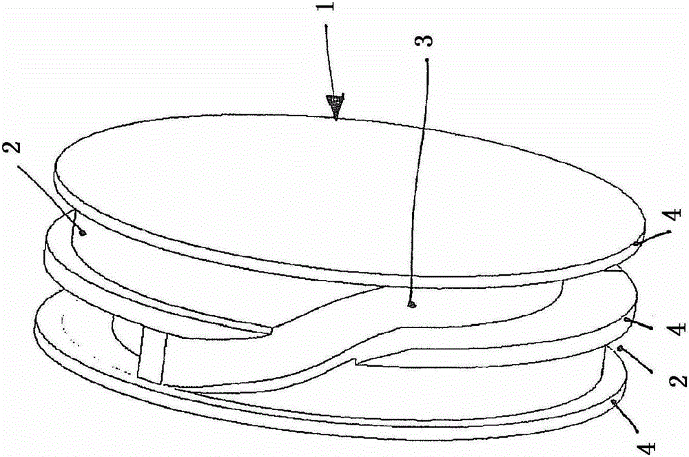
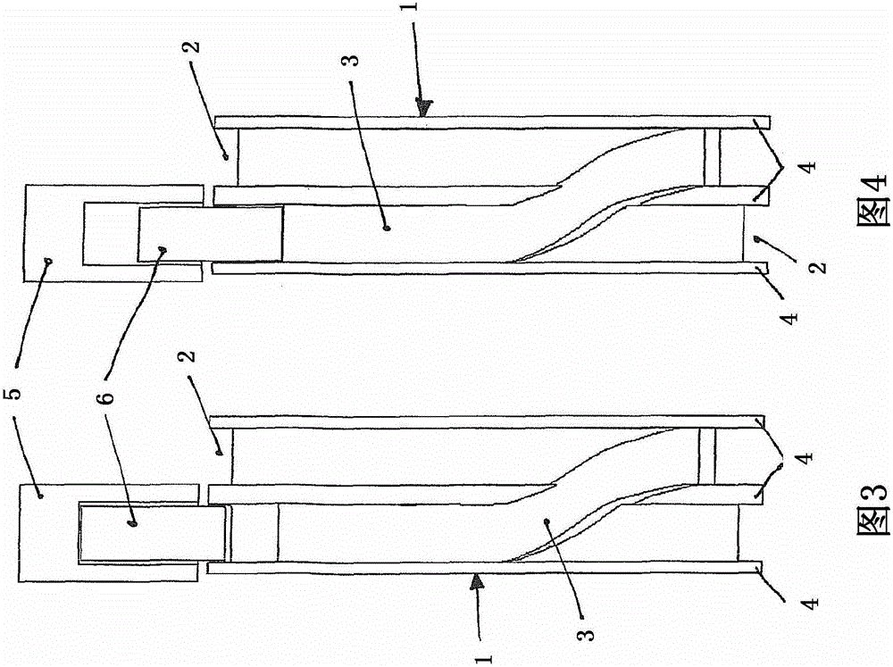
[0026] exist Figure 1 to Figure 9 In the detailed description of , the sliding cam is denoted by the reference numeral 1, as especially in Figure 7 and Figure 8 As described in , sliding cams have cam discs with different strokes but the same base circle on both sides of the adjustment and stop areas. Furthermore, the sliding cam 1 has a locking groove 2 and a sliding groove 3 between the cam discs. The detent groove 2 is delimited by a guide contour 4 which protrudes from the cylindrical region of the sliding cam 1 . Sliding grooves 3 are machined between two adjacent detent grooves 2 in order to facilitate the sliding of the sliding cam 1 on the shaft not shown, so that the cam discs can be independently activated with the operating elements not shown connection in order to initiate a corresponding upward movement at the gas exchange valve. as especially from Figure 4 and Figure 5 As can be seen in , the sliding groove 3 is machined in the deeper circumferential r...


PUM


Abstract

A sliding cam system with a sliding cam (1) which is arranged in a rotationally fixed but axially sliding manner on a base shaft, preferably on a camshaft used as a piston-reciprocating internal combustion engine The sliding cam system also has at least one removable actuating pin (6), preferably electromagnetically actuated, for sliding on the A device for adjusting the sliding cam to different axial positions on the peripheral surface of the sliding cam, wherein the adjustment device (5) is fixedly arranged on a component of the internal combustion engine; Device for locking the sliding cam ( 1 ) in position, wherein the locking device has at least one recess in each case which is assigned to an axial position, wherein the recess is designed as a locking groove on the peripheral surface of the sliding cam ( 1 ) (2), and wherein the moving-in and moving-out areas of the sliding grooves (3) lie on the plane of two adjacent stop grooves (2).

Description

technical field [0001] The invention relates to a sliding cam system with a sliding cam which is arranged in a rotationally fixed manner but axially slidable on a base shaft, preferably on a camshaft for a reciprocating internal combustion engine with pistons on the shaft; the sliding cam system has at least one removable actuating pin, preferably electromagnetically operated, for adjusting the sliding cam on its peripheral surface by means of sliding grooves cooperating with the actuating pin to different axial positions, wherein the adjustment device is fixedly arranged on a component of the internal combustion engine; and the sliding cam system also has a device for stopping the sliding cam at different axial positions, wherein the stop The actuator has at least one recess assigned to an axial position. Background technique [0002] A sliding cam system of this type is known from EP-0798451A1. The sliding cams of this system slide on the shaft via sliding grooves in suc...

Claims


Application Information

Patent Timeline
Patent Type & Authority Patents(China)
IPC IPC(8): F01L13/00
CPCF01L13/0036F01L2013/0052Y10T74/2102F01L13/00
Inventor 安德烈亚斯·内德尔
Owner SCHAEFFLER TECH AG & CO KG
Why Eureka
Try Eureka