Self-retracting device and drawer slide

An automatic, driven parts technology, applied in drawers, furniture parts, household appliances, etc., can solve problems such as high inventory costs, shell damage, etc.

Active Publication Date: 2012-11-14
PAUL HETTICH
View PDF7 Cites 5 Cited by
  • Summary
  • Abstract
  • Description
  • Claims
  • Application Information

AI Technical Summary

Problems solved by technology

[0004] The large number of different such accumulators necessary to assemble the automatic pull-in devices installed for different applications leads to relatively high inventory costs
Furthermore, in particular tension springs with a large spring constant can only be hung in the tensioning mechanism of the automatic retraction device when the automatic retraction device is installed, because otherwise the housing of the automatic retraction device would be damaged due to the high tension force of the tension spring. the threat of injury

Method used


Image

  • Self-retracting device and drawer slide
  • Self-retracting device and drawer slide
  • Self-retracting device and drawer slide

Examples


Embodiment Construction

[0026] In the following description of the drawings, concepts such as up, down, left, right, front, back, etc. are only related to the selected exemplary presentation and positions of the automatic pull-in device and other parts in the corresponding drawings. These concepts are not to be understood in a restricted manner, ie, these relationships can be changed by different working positions or a mirror-symmetrical design, etc.

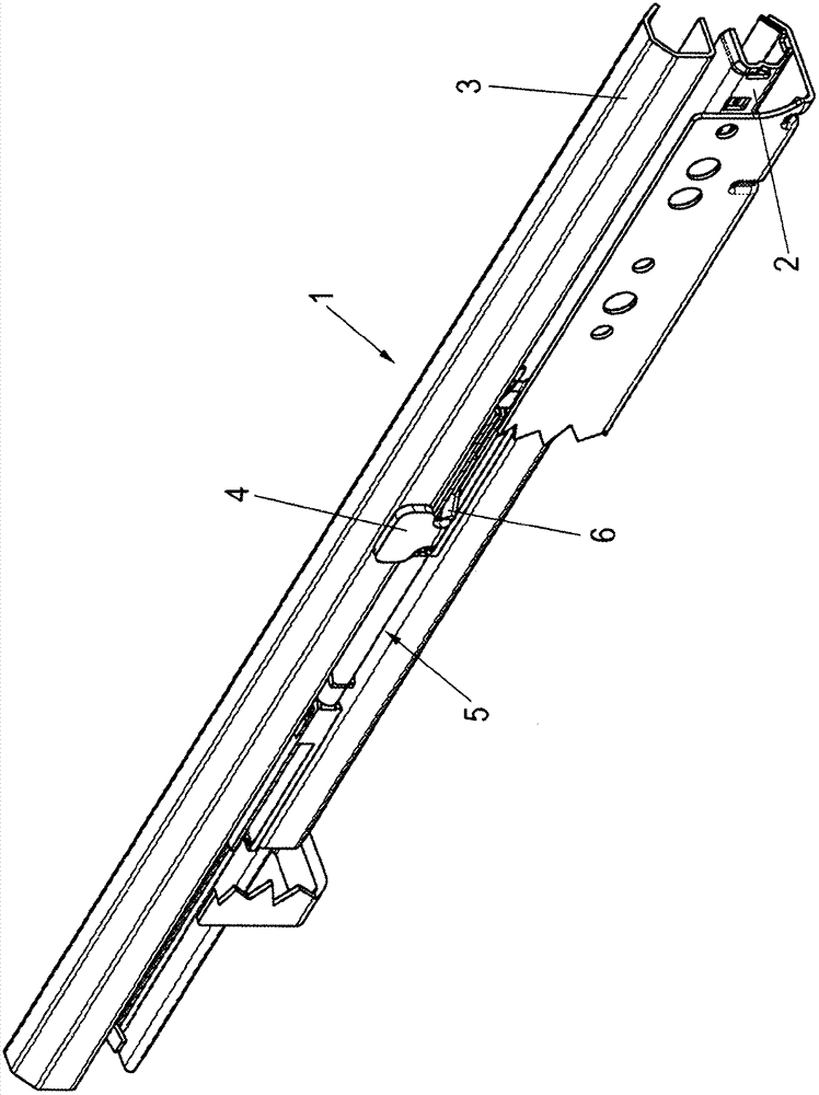
[0027] exist figure 1 The overall pull-out guide is designated with reference numeral 1 . The pull-out guide has a guide rail 2 which can be fastened to the furniture body, a working rail 3 movable on this guide rail, and an intermediate rail which may be arranged between the guide rail and the working rail. A trigger 4 is arranged on the working rail 3 , which engages in a carrier 6 of an automatic retraction device 5 , wherein the automatic retraction device 5 is arranged on the guide rail 2 .

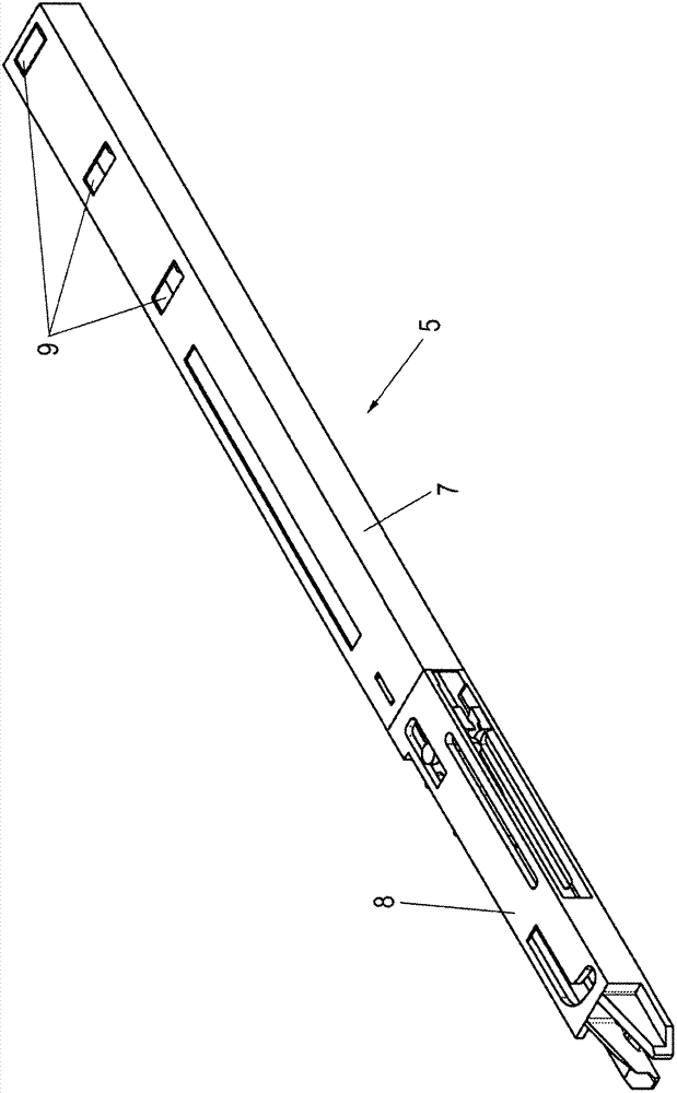
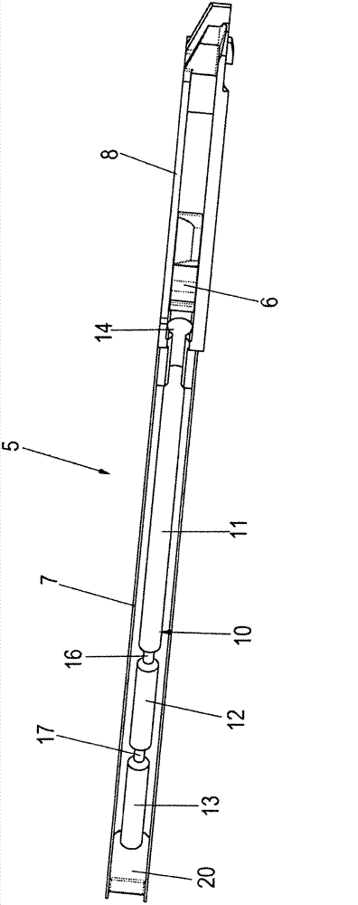
[0028] Figure 2 to Figure 10 The illustrated automa...


PUM


Abstract

The invention relates to a self-retracting device (5) of a displaceable furniture part, comprising a housing (7, 8), at least one energy store (10) disposed on the housing and that can be tensioned when the displaceable furniture part is opened, a tensioning mechanism operationally connected to the at least one energy store (10) for pretensioning the at least one energy store against a driver (6) displaceably disposed on the housing, wherein the at least one energy store (10) is divided into at least two segments (11, 12, 13), wherein the functional length of the energy store (10) is adjustable by at least one fixing element (20, 21) releasably lockable to the housing (7, 8) and engaging between two segments (11, 12, 13) of the energy store (10). The invention further relates to a drawer slide.

Description

technical field [0001] The invention relates to an automatic pull-in device for movable furniture parts according to the preamble of claim 1 and a device for drawers, sliding doors, furniture drawers according to the preamble of claim 10 Pull-out guides for automatic pull-in devices for pull-in parts or the like. Background technique [0002] Automatic pull-in devices and pull-out guides of the aforementioned type are known from the prior art in numerous embodiments. In this case, the automatic pull-in device basically consists of an energy store arranged on a housing that is fastened to rails fastened to the body of the furniture, wherein when a drawer, a furniture pull-out or the like is pulled from the closed position When pulling out, the accumulator is tensioned by the coupling of the automatic pull-in device to the trigger, wherein the trigger is fastened to a working rail which is fastened on its side to a drawer, furniture pull-out or similar and is movable on rail...

Claims


Application Information

Patent Timeline
Patent Type & Authority Applications(China)
IPC IPC(8): A47B88/04
CPCA47B88/047A47B88/467
Inventor G·巴布克-伦特B·迈尔A·施图费尔A·克特勒H·迈尔R·赫尔佐克D·米歇尔斯沃斯G·林贝格L·施鲁博克
Owner PAUL HETTICH
Why Eureka
Try Eureka