Production machine for non-circular workpieces

A non-circular, machine tool technology, applied in the direction of manufacturing tools, controlling mechanical energy, tool holder accessories, etc., can solve the problems that rolling bearings cannot be considered, machine tools are expensive, and are prone to failures

Active Publication Date: 2011-07-13
J G WEISSER SOHNE
View PDF3 Cites 3 Cited by
  • Summary
  • Abstract
  • Description
  • Claims
  • Application Information

AI Technical Summary

Problems solved by technology

The pulse decoupling is used here to prevent shocks from being transmitted with full strength by the highly dynamic tool movement to the housing or the anchorage on the housing, which could lead to adverse effects on the machining accuracy
[0003] "Entwicklung und Einsatz einer hochdynamischen Werkzeugzustelleinheit mit hydrostatischer Lagerung, Forschungsgemeinschaft" by M. Weck, J. Hennig e.V., Aachen, October 2002 "It is known that static friction aerostatic or hydrostatic guides in order to avoid the so-called stick-slip effect when guiding the tool holder meet the requirements for precision and uniformity of movement, while Due to the high dynamics of the system, the use of rolling bearings cannot be considered when the travel paths are at the same time small
[0004] However, hydrostatic guides require a high structural complexity due to the conveying lines, supply devices and measures for preventing leakage.
Due to this higher structural expense manufacturing machine tools become more expensive, prone to failure when operating in harsh environmental conditions, and require extensive maintenance

Method used


Image

  • Production machine for non-circular workpieces
  • Production machine for non-circular workpieces
  • Production machine for non-circular workpieces

Examples


Embodiment Construction

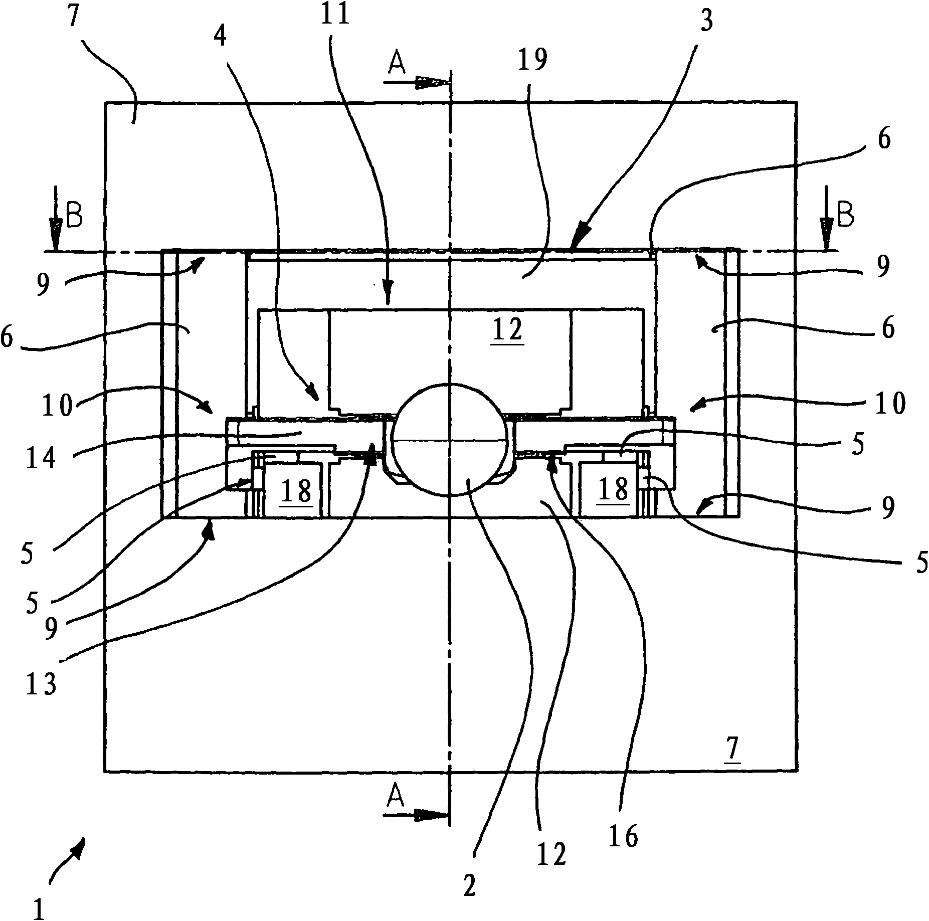
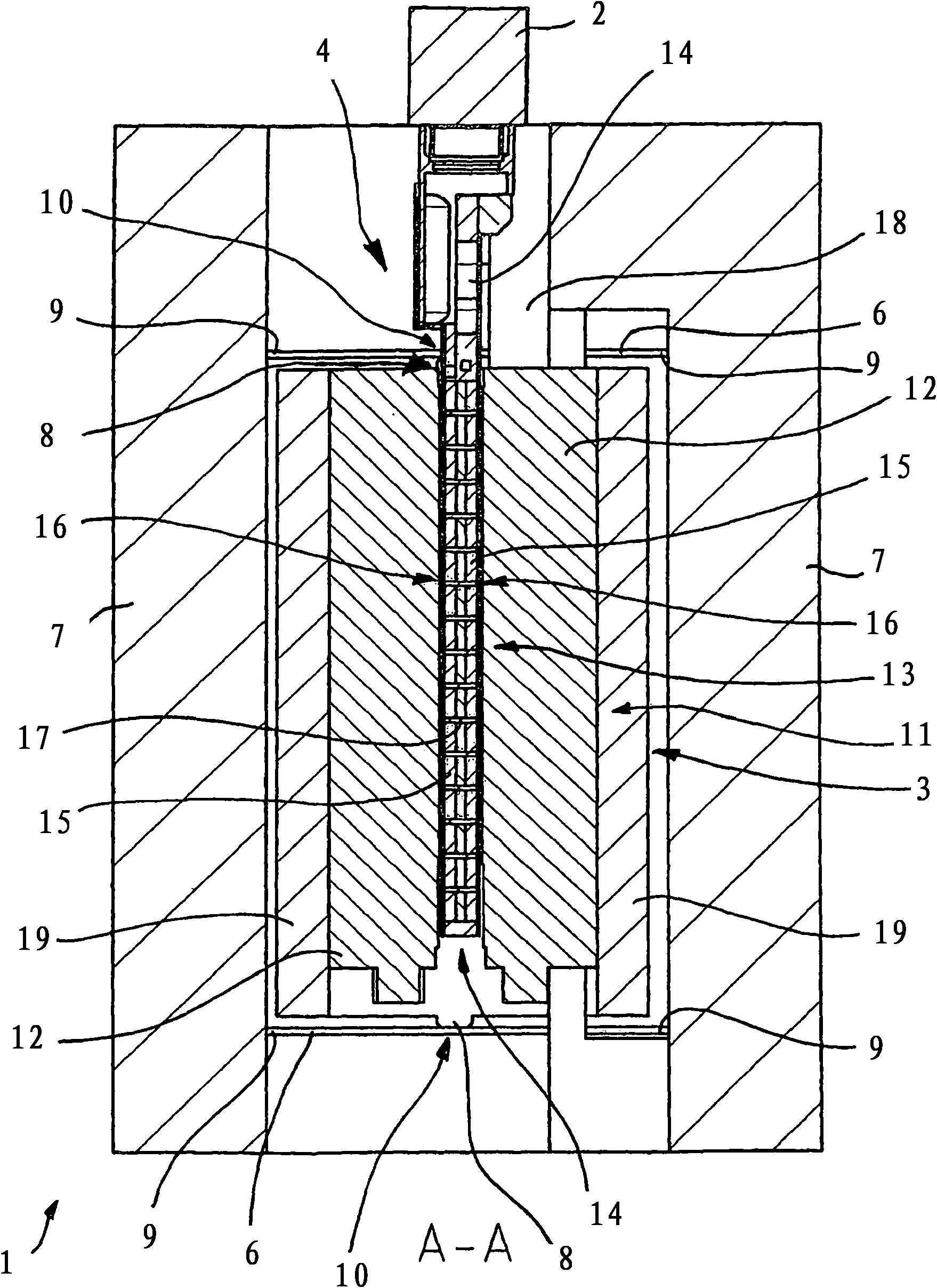
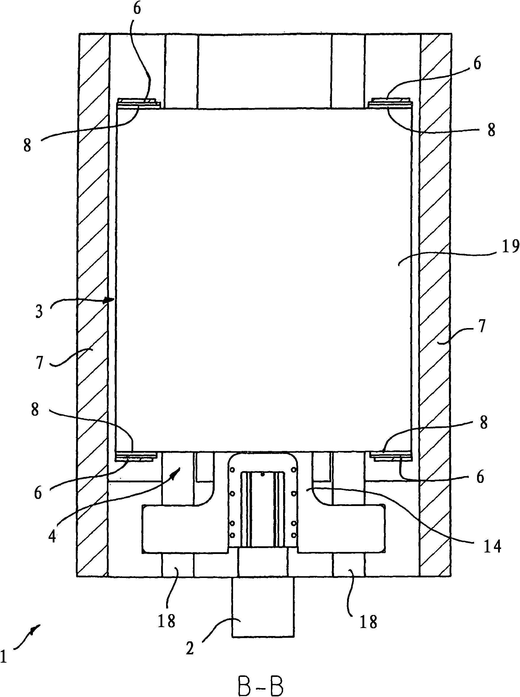
[0032] A tool feed unit, generally designated 1 , of a production machine tool for non-circular workpieces has a tool holder 2 which is designed to receive a tool and is capable of reciprocating movement.

[0033] A compensating body 3 is used for pulse decoupling, wherein the movement of the tool can be triggered or realized by a drive 4 acting between the tool holder 2 and the compensating body 3 . The acceleration of the tool carrier 2 triggered or forced by the drive 4 forms a recoil force which is absorbed by a corresponding movement of the compensating body 3 . The recoil forces thus do not act on other parts of the production machine and thus do not have a negative effect on the machining accuracy.

[0034] The tool holder 2 , which consists of or is connected to several parts, is supported by rolling elements 5 and is guided in such a way that only one degree of freedom of movement remains, namely the advance of the tool clamped on the tool holder 2 .

[0035] The com...


PUM


Abstract

The invention relates to a production machine for non-circular workpieces provided with a tool feed unit (1) comprising a tool carrier (2) for receiving the tool and a compensation body (3) for impulse decoupling, wherein the work movement of the tool carrier (2) can be effected by a drive (4) acting between the tool carrier (2) and the compensation body (3). According to the invention, the tool carrier (2) is supported by rolling bodies (5) and the compensation body (3) is suspended via elastically deformable guide elements (6) at a housing part (7) of the tool feed unit (1), wherein the mass of the compensation body (3) is larger than the mass of the tool carrier (2) carrying the tool so that the working movements of the tool carrier (2) effect compensation strokes of the compensation body (3) that are only within the range of the elastic deformability of the guide elements (6). The guide elements (6) thus effect the guiding and resetting of the compensation body (3).

Description

technical field [0001] The invention relates to a manufacturing machine tool for non-circular workpieces, especially a non-circular lathe, which has a reciprocating tool and a tool holder, and a tool for pulse deactivation that can move in reverse relative to the tool and the tool holder. A coupled compensating body, wherein the movement of the tool can be triggered or realized by a drive acting between the tool holder and the compensating body. Background technique [0002] Such a production machine tool is known, for example, from DE 198 10 996 A1 and is used in particular for high-speed production of non-circular turned components or generally in highly dynamic tool feed units. The pulse decoupling serves here to prevent impacts being transmitted with full intensity by the highly dynamic tool movement to the housing or the anchorage on the housing, which would have a negative effect on the machining accuracy. [0003] "Entwicklung und Einsatz einer hochdynamischen Werkze...

Claims


Application Information

Patent Timeline
Patent Type & Authority Applications(China)
IPC IPC(8): B23Q11/00H02K41/02F16F15/073
CPCH02K41/031B23Q11/0035H02K5/24H02K7/02Y10S82/904B23B37/00H02K7/08F16F15/073Y10T82/2533B23Q11/00
Inventor R·约尔格
Owner J G WEISSER SOHNE
Why Eureka
Try Eureka