
Compensation tank for a hydraulic motor vehicle brake system

A technology of hydraulic brake and container, applied in the direction of hydraulic brake transmission, etc., can solve the problems of loss and forget to install, and achieve the effect of eliminating the effect of the filter and avoiding the cost of the mold

Active Publication Date: 2010-06-16
CONTINENTAL AUTOMOTIVE TECH GMBH
View PDF1 Cites 6 Cited by
  • Summary
  • Abstract
  • Description
  • Claims
  • Application Information

AI Technical Summary

Problems solved by technology

However, the disadvantage of this filter is that it can be lost or forgotten to install

Method used


Image

  • Compensation tank for a hydraulic motor vehicle brake system
  • Compensation tank for a hydraulic motor vehicle brake system
  • Compensation tank for a hydraulic motor vehicle brake system

Examples


Embodiment Construction

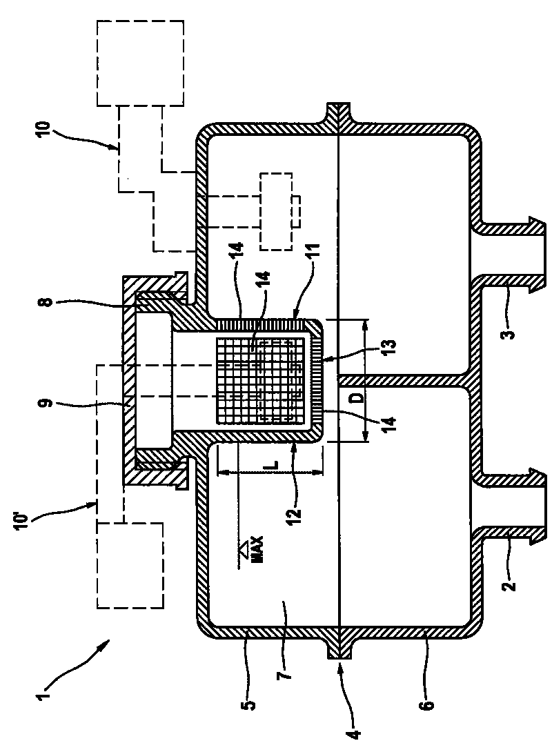
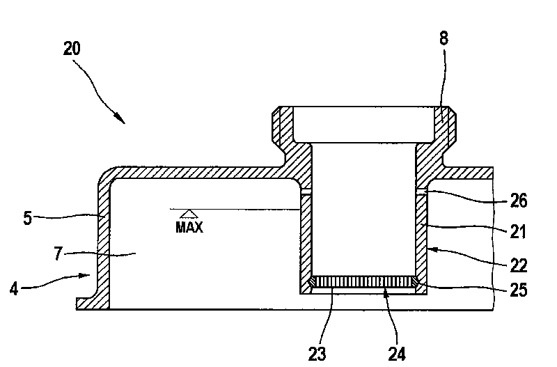
[0029] Figure 1 to Figure 5 An embodiment of a resupply container 1 , 20 , 40 according to the invention is shown, the structure and function of which substantially correspond to those of known resupply containers.

[0030] Such as figure 1 As shown, the supply container 1 is usually connected via container sockets 2 , 3 to a master cylinder (not shown) and fastened thereto. The replenishment container 1 has a housing 4 with at least one pressure medium chamber 7, wherein the housing 4 comprises a housing upper part 5 and a housing lower part 6, which at their edges and the not-shown partition walls are welded to each other.

[0031] For filling the replenishment container 1 , a cylindrical filling connection 8 is provided which protrudes at right angles from the upper side of the housing upper part 5 . The cap 9 is used to close the filling connection 8 . In order that the changing liquid level does not cause a pneumatic pressure to build up, structures are provided for ...


PUM


Abstract

The invention relates to a compensation tank (1, 20) for a hydraulic motor vehicle brake system having a housing (4) having at least one pressure medium chamber (7), the housing (4) preferably comprising an upper housing part (5) and a lower housing part (6), a tank warning device (10, 10') for monitoring the tank fill level of the compensating tank (1, 20), a filling port (8) for filling the compensation tank (1, 20), a cover (9) for sealing the filling port (8) in a liquid-tight fashion, means for pressure compensation of the compensation tank (1, 20) and preferably a cup-shaped filling filter (11, 22) disposed in the region of the filling port (8) and having a wall (12, 21) and a floor (13, 24). In order to provide a cost-effective compensation tank that is simple to install, the filling filter of which securely prevents introduction of contaminants, the invention proposes that the wall (12, 21) of the filling filter (11, 22) be formed on the housing (4) of the compensation tank (1, 20) and extend adjacent to the tank filling port (8) into the pressure medium chamber (7).

Description

technical field [0001] The present invention relates to a replenishment vessel / fluid reservoir for an automotive hydraulic braking system. Background technique [0002] A brake fluid container is known, for example, from DE 19754431 A1, which has a filler neck protruding from the housing and a filter screen located in the filler neck. A fine-meshed, correspondingly extremely effective strainer necessarily slows down the liquid injection process considerably, so that the strainer is often removed or omitted without permission. Therefore, to avoid unauthorized removal of the filter, it is recommended to use safety measures. Others suggest the use of separate ventilation openings which should improve the flow rate through the filter. However, it is especially conceivable during extremely rapid, especially automated, pressurized filling that separate vents are used inappropriately and impermissibly to bypass the filter screen and thus allow unfiltered pressure medium to enter ...

Claims


Application Information

Patent Timeline
Patent Type & Authority Applications(China)
IPC IPC(8): B60T11/26
CPCB60T11/26
Inventor P·坦德勒S·施利希特H-J·诺伊曼
Owner CONTINENTAL AUTOMOTIVE TECH GMBH
Learn More