Fault determination method and device, electronic equipment and storage medium

A determination method and fault technology, applied in the field of gearboxes, can solve problems such as large differences in actual speed and untrue output data of speed sensors

Active Publication Date: 2022-05-10
SHENGRUI TRANSMISSION
View PDF7 Cites 0 Cited by
  • Summary
  • Abstract
  • Description
  • Claims
  • Application Information

AI Technical Summary

Problems solved by technology

However, in practice, the fault that the output data of the speed sensor is not true often occurs
Specifically, the rotational speed sensor can output the collected rotational speed signal smoothly, but the output rotational speed signal is quite different from the actual rotational speed of the rotating part collected.

Method used


Image

  • Fault determination method and device, electronic equipment and storage medium
  • Fault determination method and device, electronic equipment and storage medium
  • Fault determination method and device, electronic equipment and storage medium

Examples


Embodiment Construction

[0036] In order to more clearly understand the above objects, features and advantages of the present disclosure, the solutions of the present disclosure will be further described below. It should be noted that, in the case of no conflict, the embodiments of the present disclosure and the features in the embodiments can be combined with each other.

[0037] In the following description, many specific details are set forth in order to fully understand the present disclosure, but the present disclosure can also be implemented in other ways than described here; obviously, the embodiments in the description are only some of the embodiments of the present disclosure, and Not all examples.

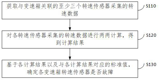
[0038] figure 1 It is a flow chart of a method for determining a gearbox speed sensor failure provided by an embodiment of the present disclosure. This method is applicable to the situation of determining whether the transmission speed sensor is faulty, and the method can be executed by the veh...


PUM


Abstract

The invention relates to a fault determination method and device, electronic equipment and a storage medium. The method comprises the following steps: acquiring rotating speed data acquired by at least three rotating speed sensors associated with a gearbox; performing pairwise calculation on the rotating speed data acquired by each rotating speed sensor to obtain a calculation result; and on the basis of each calculation result and a standard value corresponding to each calculation result, determining whether each gearbox rotating speed sensor has a fault or not. By adopting the technical scheme provided by the embodiment of the invention, whether the rotating speed sensor has a fault of unreal output data can be identified.

Description

technical field [0001] The present disclosure relates to the technical field of gearboxes, and in particular to a fault determination method, device, electronic equipment and storage medium. Background technique [0002] The gear ratio of the gearbox is equal to the input shaft speed divided by the output shaft speed. In order to better control the gearbox, the TCU (Transmission Control Unit, gearbox controller) needs to obtain the input shaft speed and output shaft speed in real time. However, in practice, the fault that the output data of the speed sensor is not true often occurs. Specifically, the rotational speed sensor can output the collected rotational speed signal smoothly, but the output rotational speed signal is quite different from the actual rotational speed of the rotating member collected. How to determine whether there is such a fault in the speed sensor is an urgent problem to be solved at present. Contents of the invention [0003] In order to solve th...

Claims


Application Information

Patent Timeline
Patent Type & Authority Applications(China)
IPC IPC(8): G01P21/02
CPCG01P21/02
Inventor 高龙辛彩云时玉珂
Owner SHENGRUI TRANSMISSION
Why Eureka
Try Eureka