

Refraction measuring device and portable optometry unit thereof
A technology of refraction measurement and optometry, applied in optometry, eye testing equipment, medical science, etc., can solve the problems of unfavorable and complicated use of refraction screening
- Summary
- Abstract
- Description
- Claims
- Application Information
AI Technical Summary
Benefits of technology
Problems solved by technology
Method used
Image

Examples
Embodiment 1
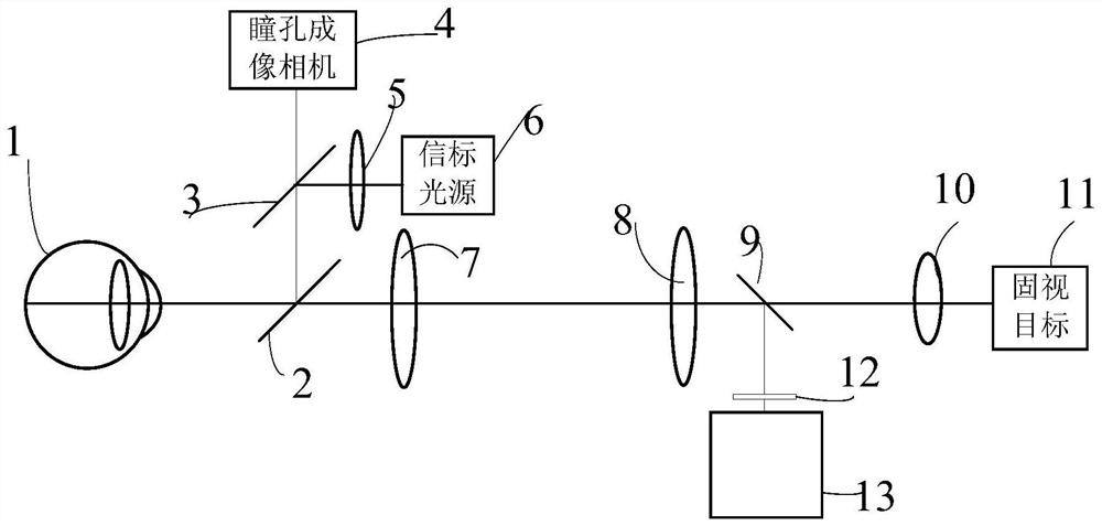
[0078] Such as figure 1 As shown, it schematically shows the optical path arrangement and measurement operation of the refraction measurement device of the present disclosure.
[0079] First, the pupil alignment step is completed for the eye 1 to be tested.
[0080] Then, turn on the detection light source, which is the beacon light source 6 in the embodiment. The light emitted by the beacon light source 6 is collimated into parallel light by the beacon light collimating lens 5 , and then enters the eye 1 to be tested through the second beam splitter 3 and the first beam splitter 2 . Then, the retroreflected light of the fundus of the eye 1 passes through the first beam splitter 2, the first focusing lens 7, the second focusing lens 8, and the third beam splitting mirror 9, and enters the spot image extraction mechanism after passing through the annular spot forming unit 12 13 (imaging device), the spot image extraction mechanism 13 collects spot images arranged in a ring or...
Embodiment 2
[0094] The difference between this embodiment and Embodiment 1 is that a multi-ring sub-lens array is used.
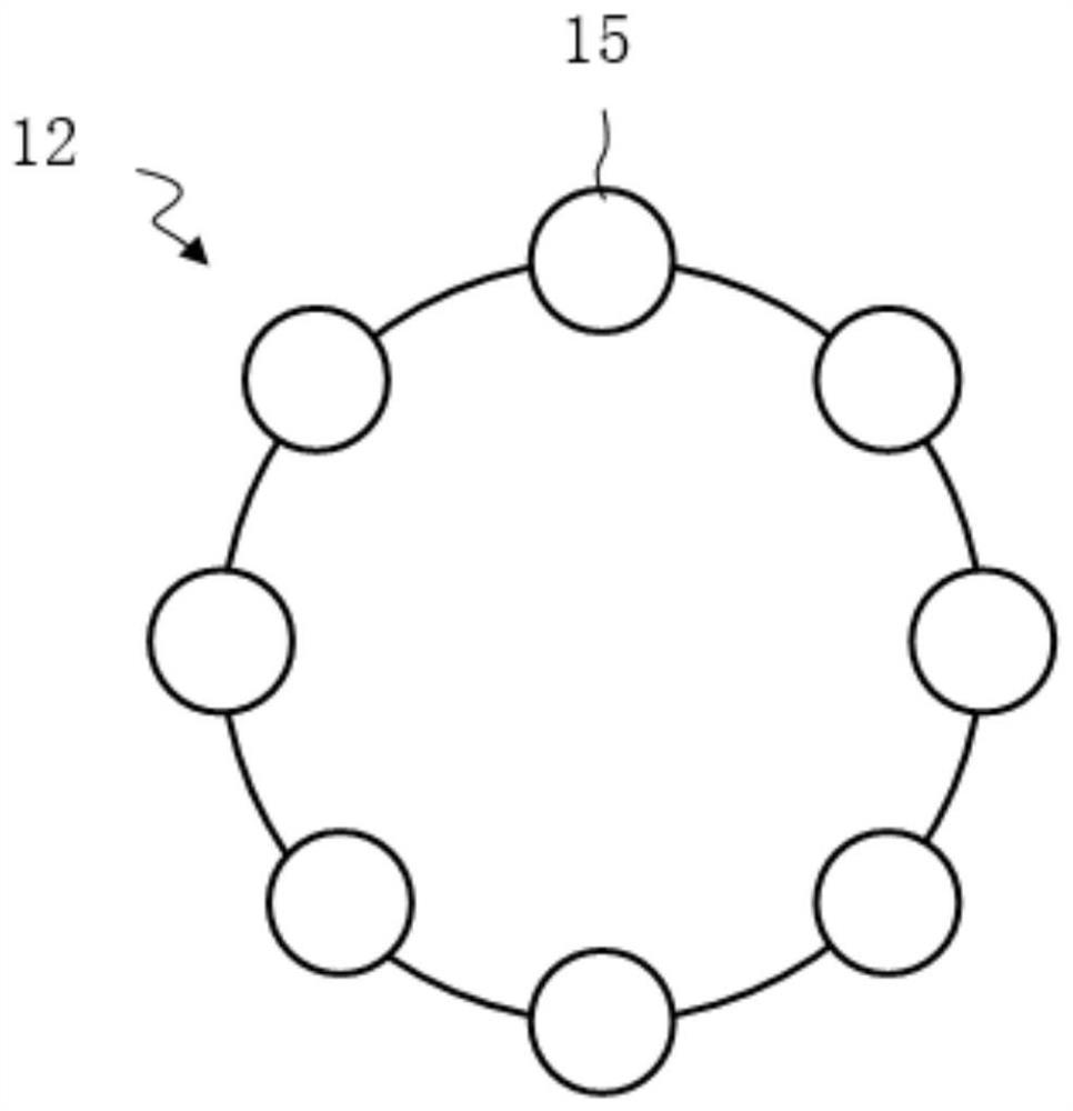
[0095] The present disclosure employs a sub-lens sub-array to achieve the effect of a ring lens. The number of sub-lens arrays N≥1. When N=1, such as figure 2 As shown, there is only one ring-arranged sub-lens array; when N=2, there are two concentric ring-arranged sub-lens arrays. In a further variant embodiment, for example, when N=3, three rings of sub-lens arrays are concentrically arranged. In a further variant embodiment, for example, when N=4, four sub-lens arrays are concentrically arranged. In a further variant embodiment, for example, when N=5, five rings of sub-lens arrays are concentrically arranged. The more concentric rings, the greater the accuracy of fitting the ellipse to calculate the diopter.
[0096] Using the sub-lens array arranged in a circle to obtain the elliptical spot is actually fitting the elliptical spot, which can effectively reduce...
Embodiment 3
[0099] The difference between this embodiment and Embodiments 1 and 2 is that the main component of the annular spot forming unit 12 is an annular lens.
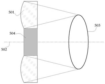
[0100] Figure 5 A ring lens arrangement is schematically shown. The configuration of the annular lens 501 is formed by using a lens section to rotate 360° around the optical axis 502 . The central portion 504 of the annular lens adopts a light-shielding or hollow design.
[0101] The diopter measurement process is as follows:
[0102] Operate pupil alignment first. After the pupil alignment step is completed, the beacon light source 6 is turned on, and the beacon light source 6 is collimated into parallel light by the beacon light collimating lens 5, and then enters the eye 1 to be tested through the second beam splitter 3 and the first beam splitter 2 . Then, the retroreflected light from the fundus of the eye 1 passes through the first beam splitter 2, the first focus lens 7, the second focus lens 8, and the third be...
PUM
 Abstract
Description
Claims
Application Information