Modular optical measurement system and optometry device

An optical measurement system and modular technology, applied in the field of computer optometry, can solve problems such as difficulty in meeting optical path design requirements, reduced instrument performance, and optical adjustment restrictions, and achieve the effects of low processing accuracy requirements, reduced assembly errors, and improved accuracy.

Active Publication Date: 2019-04-12
重庆远视科技有限公司
View PDF8 Cites 0 Cited by
  • Summary
  • Abstract
  • Description
  • Claims
  • Application Information

AI Technical Summary

Problems solved by technology

At present, the traditional computer optometry mostly adopts a simple integrated layout. The parts are assembled on the installation frame. Due to limitations, it is impossible to make up for the errors caused by the part manufacturing process and the sy

Method used


Image

  • Modular optical measurement system and optometry device
  • Modular optical measurement system and optometry device
  • Modular optical measurement system and optometry device

Examples


Embodiment Construction

[0025] The core of the present invention is to provide a modularized optical measurement system, which can be adjusted during the assembly process through a detachable and fixedly installed structure, so as to improve the accuracy of the optical path and reduce assembly errors.

[0026] In order to enable those skilled in the art to better understand the technical solution of the present invention, the modular optical measurement system of the present invention will be described in detail below in conjunction with the accompanying drawings and specific implementation methods.

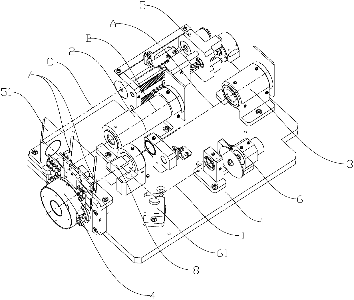
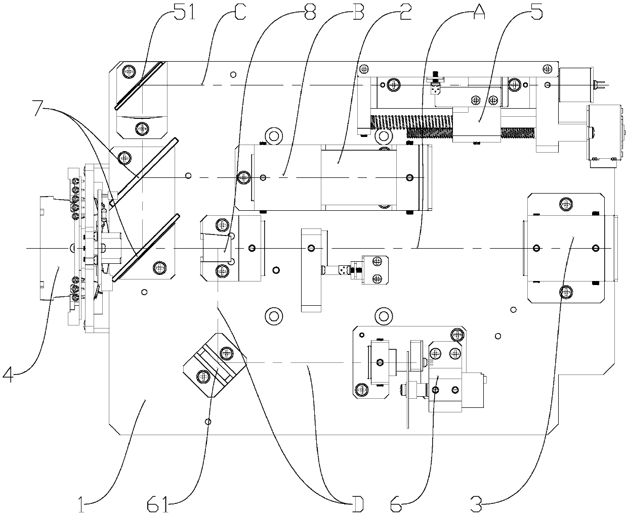
[0027] Such as figure 1 As shown, it is the axonometric structure diagram of the modularized optical measurement system provided by the present invention, figure 2 The top view of the modular optical measurement system provided by the present invention, wherein the dotted line A represents the optical path of refraction measurement, B represents the optical path of cornea measurement, C represents the ...


PUM


Abstract

The invention discloses a modular optical measurement system. The upper surface of a mounting base plate is flat, and the upper surface of the mounting base plate is detachably and fixedly provided with the following structures: a cornea measuring device, a diopter measuring device, the Meyer ring, a scieropia target and an illuminating device; the optical paths of the Meyer ring and the diopter measuring device are provided with a spectroscope, a splitting prism and a compensating mirror in turn; the light entering from the Meyer ring enters the corneal measuring device through the spectroscope; the light of the scieropia target enters the Meyer ring through a scieropia reflector and the spectroscope; and the light of the illuminating device enters the Meyer ring through the reflector andthe spectroscope. Since the structures of the cornea measuring device, the diopter measuring device and the mounting base plate are all independent and detachable, requirement on the processing precision of the mounting base plate is low, and only a flat upper surface needs to be guaranteed. When other components are assembled on the mounting base plate, the micro-adjustment can be realized by amounting structure; and as the position is accurate, the components are relatively fixed so as to improve the accuracy of the optical path and to reduce the assembly error.

Description

technical field [0001] The invention relates to the technical field of computerized optometry, and further relates to a modularized optical measurement system. In addition, the invention also relates to an optometry device. Background technique [0002] The computer refractor is a widely used ophthalmic examination instrument. The optical path is complex. During the assembly process, the installation of optical parts needs to be fine-tuned to ensure the stability of the optical path and the accuracy of measurement. At present, the traditional computer refractometer mostly adopts a simple integrated layout, each part is assembled on the installation frame, the installation frame is an integrated structure, and the installation position of each part is set on it, and the position of each part is uniquely determined, resulting in light adjustment. Due to limitations, it is impossible to make up for the errors caused by the part manufacturing process and the system errors in th...

Claims


Application Information

Patent Timeline
IPC IPC(8): A61B3/103
CPCA61B3/103
Inventor 胡冰朱建国
Owner 重庆远视科技有限公司
Why Eureka
Try Eureka