
A Correction Method for Starlight Atmospheric Refraction Measurement Based on Refractive Surface Collinearity

A technology of atmospheric refraction and measurement correction, which is applied in the field of starlight atmospheric refraction measurement correction, can solve the problems that the uniformity of the medium is difficult to meet, affects the accuracy of atmospheric refraction correction, and the accuracy of atmospheric refraction correction is difficult to guarantee.

Active Publication Date: 2021-09-07
BEIHANG UNIV
View PDF4 Cites 0 Cited by
  • Summary
  • Abstract
  • Description
  • Claims
  • Application Information

AI Technical Summary

Problems solved by technology

First of all, the refractive index of each incident direction in the actual earth's atmosphere is different, so the theoretical homogeneous layered spherical atmospheric model is isotropic and the properties of the medium are difficult to satisfy, and the accuracy of atmospheric refraction correction in the actual application process is difficult to guarantee
Secondly, these methods all need the help of other instruments to measure the propagation environment of starlight in the atmosphere, such as temperature, pressure, humidity, etc. These instruments add their measurement errors to the correction results in the process of correcting starlight atmospheric refraction, which will affect Accuracy of Atmospheric Refraction Correction
Finally, these methods do not have the ability to correct for atmospheric refraction of multiple stars with changing observation positions in real time with high precision

Method used


Image

  • A Correction Method for Starlight Atmospheric Refraction Measurement Based on Refractive Surface Collinearity
  • A Correction Method for Starlight Atmospheric Refraction Measurement Based on Refractive Surface Collinearity
  • A Correction Method for Starlight Atmospheric Refraction Measurement Based on Refractive Surface Collinearity

Examples


Embodiment Construction

[0044] The present invention will be described in detail below in conjunction with the accompanying drawings and embodiments.

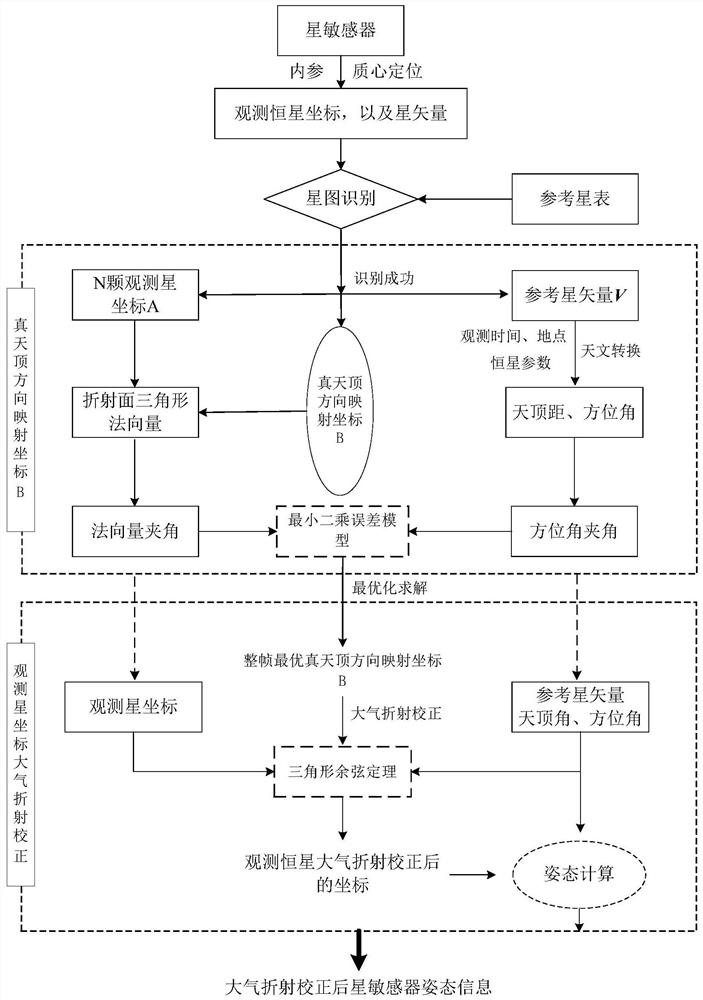
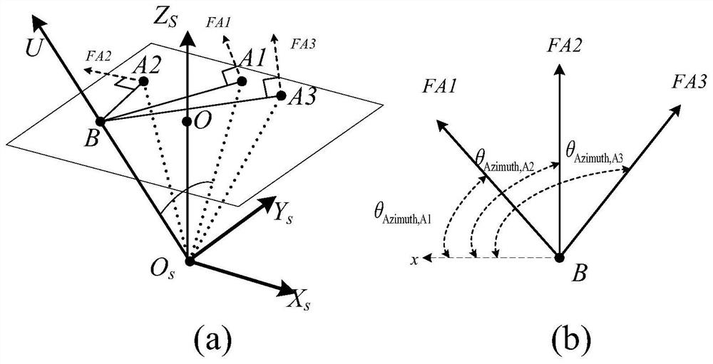
[0045] like figure 1 As shown, the present invention proposes a real-time atmospheric refraction correction measurement method based on refraction plane collinearity. This method is based on the coplanarity of atmospheric refraction, that is, atmospheric refraction only changes the zenith angle of incident light without affecting its incident azimuth. Based on this, different observed stars in the star sensor have their own atmospheric refraction surfaces. Without considering other errors, the atmospheric refraction planes of all observed stars intersect in a straight line, which is the direction of the earth's zenith at the observation time and position of the star sensor.

[0046] Although factors such as pressure, temperature, humidity and other factors at various positions where starlight passes through the trajectory of the atmosphere will affe...


PUM


Abstract

The invention relates to a starlight atmospheric refraction measurement correction method based on collinear refraction surfaces, which is based on star vectors observed by star sensors and reference star catalogs for star map identification to obtain the matching relationship between observed stars and reference stars; The reference star vector is converted to the geographic coordinate system before entering the atmosphere to obtain the zenith distance and azimuth of the incident starlight; based on the collinear principle of the refraction surface, the imaging coordinates of all stars identified according to the star map and their azimuth before entering the atmosphere The position coordinates of the zenith direction on the imaging surface of the star sensor are obtained by optimizing the solution; according to the position coordinates of the optimal zenith direction on the imaging surface obtained by the solution, the coordinates of the image surface coordinates of all the observed stars identified are calculated using the trigonometric cosine formula Atmospheric refraction correction to obtain the corrected star coordinates; solve to obtain the attitude of the star sensor in the geographic coordinate system.

Description

technical field [0001] The invention relates to a method for measuring and correcting starlight atmospheric refraction based on collinear refraction surfaces, and belongs to the technical field of starlight atmospheric refraction correction in star sensitivity. Background technique [0002] As an important factor affecting the attitude measurement accuracy of the ground-based star sensor, the refraction effect of the atmosphere on the incident starlight is a key issue that restricts the high attitude measurement accuracy of the ground-based star sensor. Although astronomers have done a lot of research on starlight atmospheric refraction in the past few decades, the real-time and high-precision starlight atmospheric refraction correction has not been effectively solved in practical applications. [0003] There are two main types of existing atmospheric refraction correction methods. The first type is the atmospheric refraction fitting model correction method based on the the...

Claims


Application Information

Patent Timeline
Patent Type & Authority Patents(China)
IPC IPC(8): G01C25/00G01C21/02
CPCG01C25/00G01C21/02G01S3/7867
Inventor 江洁王振
Owner BEIHANG UNIV
Learn More