
Anti-crosswind warning device and bridge

A warning device and cross-wind technology, which is applied to bridges, bridge construction, bridge parts, etc., can solve problems such as car crashes, decreased vehicle grip, and deviation of driving direction, so as to improve driving safety and reduce cross-wind volume Effect

Pending Publication Date: 2022-05-13
陈俊涵
View PDF8 Cites 0 Cited by
  • Summary
  • Abstract
  • Description
  • Claims
  • Application Information

AI Technical Summary

Problems solved by technology

The occurrence of cross wind has the characteristics of suddenness, short time and strong wind. Although the time of cross wind occurs is short, but its intensity is very strong. The impact of the vehicle is relatively large
When the cross wind blows, the grip of the vehicle will decrease, and the driving direction will deviate. Improper handling will directly lead to the rollover of the vehicle and cause a major accident of car crash and death

Method used


Image

  • Anti-crosswind warning device and bridge
  • Anti-crosswind warning device and bridge
  • Anti-crosswind warning device and bridge

Examples


Embodiment 1

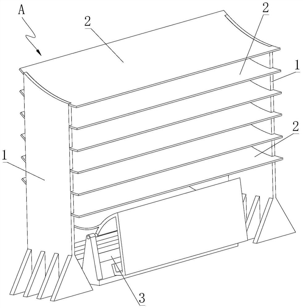
[0027] Such as figure 2 As shown, a warning device A for preventing cross wind, its structure includes two sets of columns 1, and the upper parts of the two sets of columns 1 are provided with wind deflectors 2 arranged in an array along the vertical direction, and the wind deflectors 2 are all arranged obliquely. The installation height of its outer end is lower than that of the inner end. In this implementation, the upper surface of the wind deflector 2 has an arc-shaped wind deflector surface. After the anti-horizontal wind warning device A is installed on both sides of the bridge, the low end of the wind deflector 2 is located on the outside, and the inclined wind deflector The crosswind can be guided above the carriageway to reduce the influence of the crosswind on the driving vehicles.

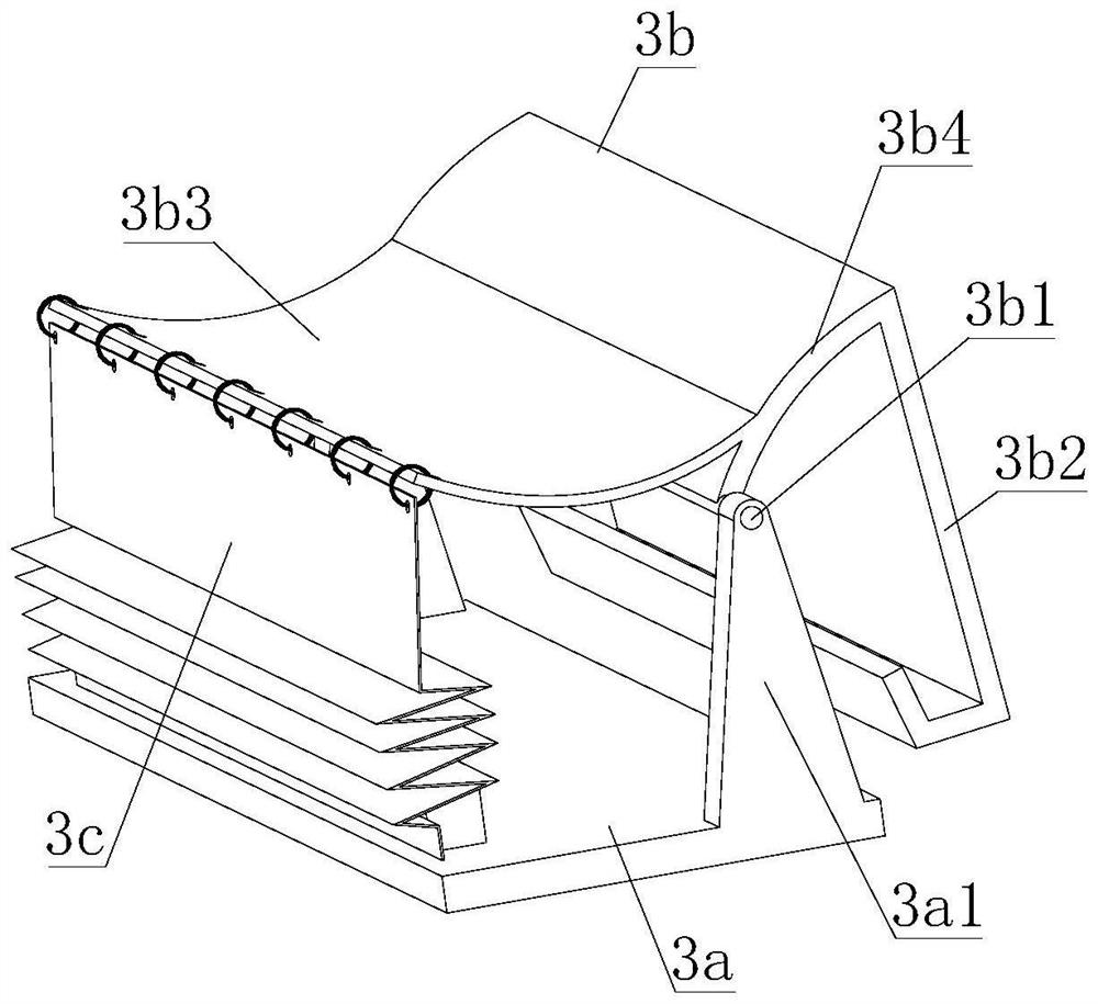
[0028] Another example image 3 As shown, an early warning mechanism 3 is provided between the lower parts of two groups of columns 1, and the early warning mechanism 3 includes a bas...

Embodiment 2

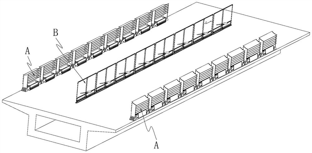
[0032] Such as figure 1 As shown, a bridge, the above-mentioned anti-crosswind warning device A is installed on both sides of the bridge, and the spiral anti-crosswind device B is installed at the central isolation zone of the bridge.

[0033] Please refer to image 3 with 4 As shown, in this embodiment, the structure of the spiral anti-crosswind device B mainly includes a support frame 7 , a spiral guide rod 8 , fan blades 9 , a cage 4 and two curtains 5 . Wherein, the supporting frame body 7 is a rectangular frame structure, and a vertically arranged positioning guide rod 7a is provided at each of its two ends. The helical guide rod 8 has a helical surface in the axial direction, and is vertically installed in the middle of the support frame 7 . The fan blade 9 is a propeller structure, which includes a central connection seat 9a and two blades 9b extending radially outward from the central connection seat 9a. The retainer 4 is connected to the lower end of the fan blade...


PUM


Abstract

The anti-crosswind warning device comprises two sets of stand columns, air guide plates distributed in an array mode in the vertical direction are arranged between the upper portions of the two sets of stand columns, the air guide plates are obliquely arranged, and the installation height of the outer ends of the air guide plates is lower than that of the inner ends of the air guide plates; an early warning mechanism is arranged between the lower portions of the two stand columns and comprises a base, a sensing component and early warning cloth, and the sensing component is provided with a supporting shaft rotationally connected with the base, a wind sensing plate located on the outer side of the supporting shaft and a connecting plate extending inwards relative to the supporting shaft. The upper end and the lower end of the early warning cloth are connected to the connecting plate and the base correspondingly. The crosswind guiding device has the beneficial effects that crosswind can be guided to the position above a traffic lane, traffic safety is guaranteed, and the warning effect can be achieved under extreme conditions.

Description

technical field [0001] The invention relates to the technical field of bridges, in particular to a cross-wind warning device and a bridge. Background technique [0002] As the name suggests, "cross wind" means the wind blowing from side to side. From the perspective of the car moving forward, it means the wind blowing from the side. The occurrence of cross wind has the characteristics of suddenness, short time and strong wind. Although the time of cross wind occurs is short, but its intensity is very strong. Vehicles have a greater impact. When the cross wind blows, the grip of the vehicle will decrease, and the driving direction will deviate. Improper handling will directly cause the vehicle to roll over and cause a major accident of vehicle crash and death. [0003] With the increase of cross-sea bridges in our country, due to the unstable air flow on the sea surface all year round, the possibility of driving vehicles encountering cross winds is also increasing. In view...

Claims


Application Information

Patent Timeline
Patent Type & Authority Applications(China)
IPC IPC(8): E01F7/02E01F9/627E01D19/00
CPCE01F7/025E01F9/627E01D19/00
Inventor 陈俊涵
Owner 陈俊涵
Learn More