

Bearing accessory and window
A technology of accessories and heavy parts, applied in the field of doors and windows, can solve the problems of poor bearing capacity of hidden hinges, and achieve the effect of large bearing capacity, low cost and strong bearing capacity
- Summary
- Abstract
- Description
- Claims
- Application Information
AI Technical Summary
Problems solved by technology
Method used
Image

Examples
Embodiment 1
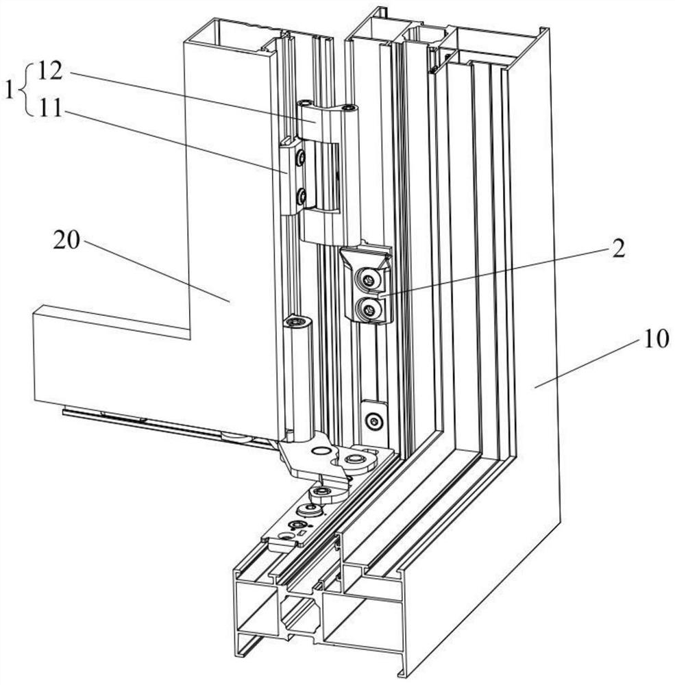
[0037] see Figure 1 to Figure 4 , the embodiment of the present invention provides a window, including a fixed window frame 10 and a movable sash 20, and also includes a load-bearing accessory. The window uses the load-bearing accessory to enable the fixed window frame 10 to carry the heavy movable sash 20, which disperses the force of the hidden hinge . The load-bearing accessory includes a hinge 1 and a load-bearing 2. The hinge 1 includes a fixing part 11 and a connecting part 12. The fixing part 11 is connected to the connecting part 12 in rotation; the connecting part 12 is slidably connected to the load-bearing part 2. The bottom of the piece 12 to support the connecting piece 12. The bearing part 2 is fixed on the side wall of the fixed window frame 10 , and the fixing part 11 is fixed on the side wall of the movable window 20 .
[0038] The load-bearing part 2 is connected with the fixed window frame 10, the fixed part 11 is connected with the movable sash 20, the f...
Embodiment 2
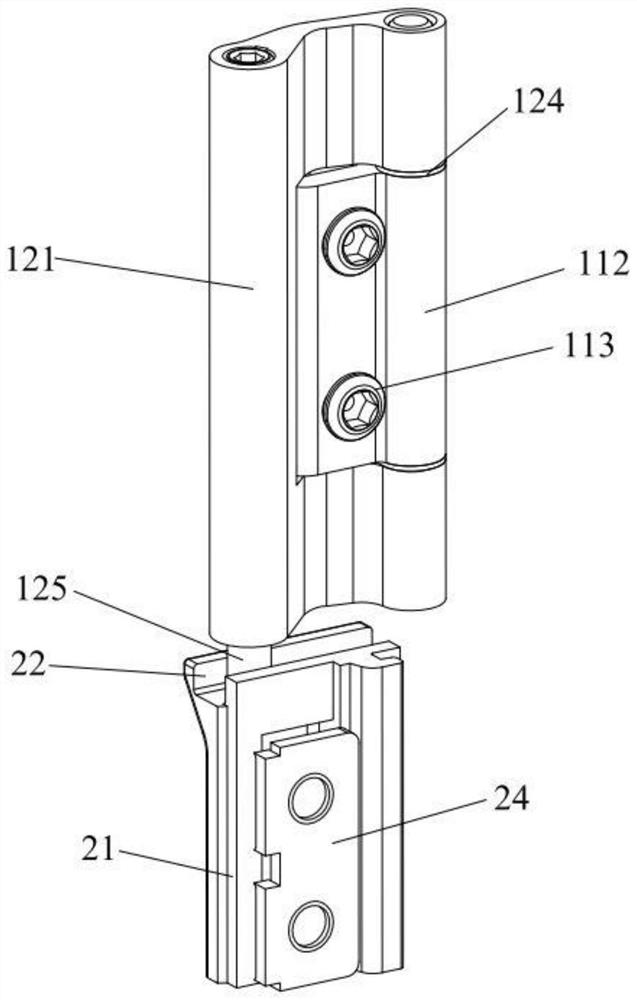
[0051] Figure 5 Embodiment 2 is shown, in which components identical or corresponding to those in Embodiment 1 are identified with reference numerals corresponding to Embodiment 1. For simplicity, only the differences between Embodiment 2 and Embodiment 1 are described. The difference is that the bearing member 2 includes a support block 21, the upper end of the support block 21 has a long protrusion 23, the bottom end of the sliding shaft 125 has a groove 127, and the bottom end of the sliding shaft 125 is slidably connected to the long protrusion 23 to realize The sliding connection between the connecting part 12 and the load-bearing part 2 is realized, the structure is simple, the processing is convenient, and the cost is low. The sliding shaft 125 can move in the height direction of the long protrusion 23, that is, this embodiment can also be applied to inwardly opening and inverting windows. , when the inner-turning window is opened, the long protrusion 23 will not rest...
Embodiment 3
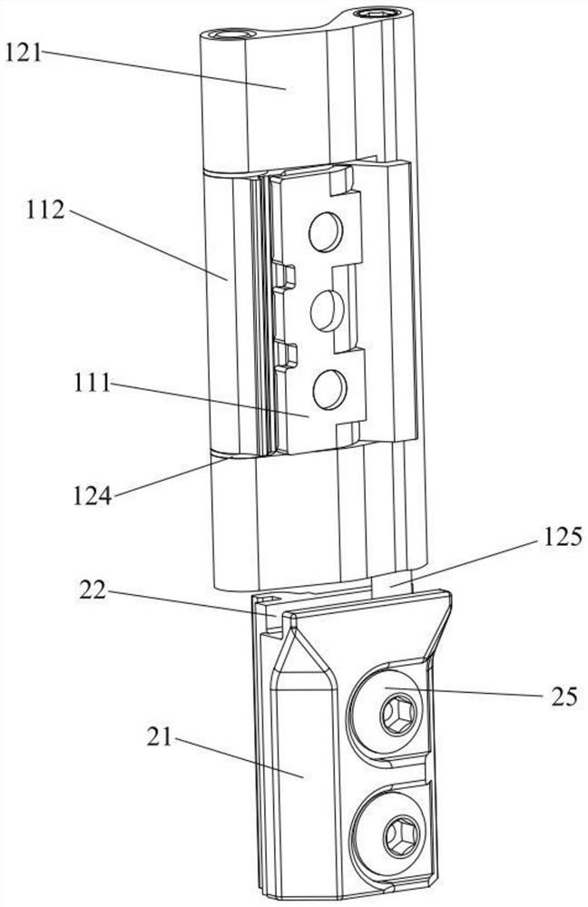
[0053] Figure 6 Embodiment 3 is shown, in which components identical or corresponding to those in Embodiment 1 are designated with reference numerals corresponding to Embodiment 1. For simplicity, only the differences between Embodiment 3 and Embodiment 1 are described. The difference is that the bearing member 2 includes a support block 21, the upper end of the support block 21 has a chute 22, the bottom end of the sliding shaft 125 is slidably connected to the chute 22, the bottom end of the sliding shaft 125 is provided with a recess 1251, and the support block The upper end of 21 has two protruding parts 211, and two protruding parts 211 are respectively located at the two sides of chute 22, and recessed part 1251 is fastened with protruding part 211 to limit sliding shaft 125 to move along the vertical direction, and protruding part 211 and the recessed part 1251 make the connection stability between the load-bearing part 2 and the hinge part 1 better. Since the recess...
PUM
 Abstract
Description
Claims
Application Information