Passage opening and closing device
A technology for opening and closing devices and passages, which can be used in transportation and packaging, noise suppression, heating/cooling equipment, etc., and can solve problems such as poor manufacturability of sliding doors
- Summary
- Abstract
- Description
- Claims
- Application Information
AI Technical Summary
Problems solved by technology
Method used
Image
Examples
no. 1 approach
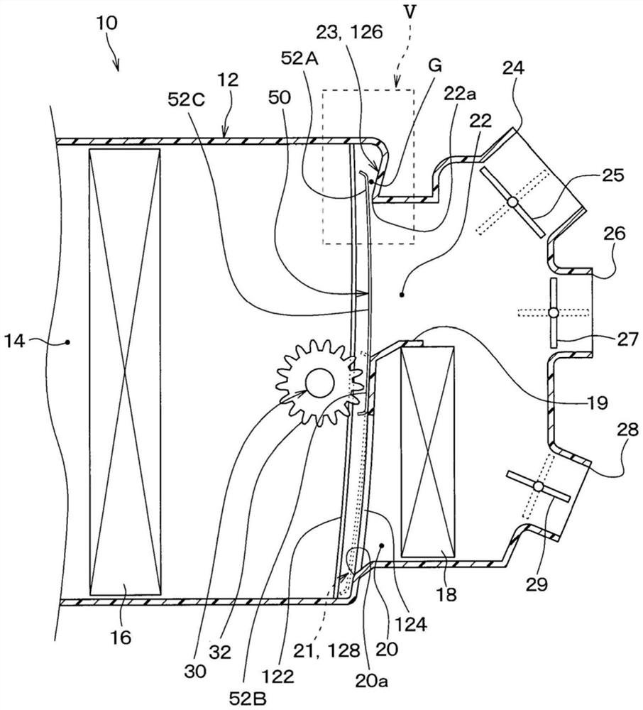
[0039] refer to Figure 1 to Figure 13 This embodiment will be described. In this embodiment, an example in which the passage opening and closing device of the present invention is applied to the indoor air-conditioning unit 10 of the vehicle air-conditioning apparatus will be described.
[0040] figure 1 The illustrated indoor air conditioner unit 10 is disposed at a substantially central portion in the vehicle width direction on the inner side of an instrument panel located at the frontmost portion in the vehicle interior. The indoor air conditioner unit 10 has a casing 12 that forms an outer shell thereof and forms an air passage for blown air blown toward the vehicle interior. The casing 12 is formed of a resin (for example, polypropylene) that has a certain degree of elasticity and is excellent in strength.
[0041] An air inflow space 14 into which blowing air from a blower unit (not shown) flows is formed on the most upstream side of the air passage formed in the cas...
no. 2 approach
[0114] Next, refer to Figure 14 A second embodiment will be described. In this embodiment, differences from the first embodiment will be mainly described.
[0115] Such as Figure 14 As shown, the cold air seal portion 126 is provided with an inclined portion 126c inclined in a stepwise manner with respect to the door moving direction DRs so as to move away from the cold air side end portion 52A as it moves away from the cool air opening 22a.
[0116] The inclined portion 126c is provided at a position facing the cold air side end portion 52A when the air mix door 50 is displaced to a position where the cool air opening 22a is closed. The inclined portion 126c is inclined stepwise with respect to the door moving direction DRs so that the distance from the cool air end portion 52A increases stepwise as the distance from the cool air opening 22a increases. In other words, the inclined portion 126c is inclined in a stepwise manner with respect to the door moving direction DRs...
no. 3 approach
[0121] Next, refer to Figure 15 A third embodiment will be described. In this embodiment, differences from the first embodiment will be mainly described.
[0122] Such as Figure 15 As shown, the inclined portion 126a is not provided in the cool air seal portion 126, and the cool air seal portion 126 extends along the door moving direction DRs. That is, the cool air seal portion 126 as a whole has a flat shape along the door moving direction DRs.
[0123] On the other hand, when the air mix door 50 is displaced to a position to close the cool air opening 22a, the cool air side end 52A of the air mix door 50 moves relative to the door in such a manner as to separate from the cool air seal 126 as it moves away from the cool air opening 22a. The directions DRs are tilted.
[0124] 52 A of cold wind side end parts are comprised so that the inclination angle (theta)d formed with the door moving direction DRs becomes an acute angle. A bending portion 52D serving as a starting ...
PUM
 Abstract
Description
Claims
Application Information
 - R&D Engineer
- R&D Manager
- IP Professional
- Industry Leading Data Capabilities
- Powerful AI technology
- Patent DNA Extraction
Browse by: Latest US Patents, China's latest patents, Technical Efficacy Thesaurus, Application Domain, Technology Topic, Popular Technical Reports.
© 2024 PatSnap. All rights reserved.Legal|Privacy policy|Modern Slavery Act Transparency Statement|Sitemap|About US| Contact US: help@patsnap.com


