
Glue injection mechanism and injection molding machine

A technology of glue injection and glue injection head plate, applied in the field of glue injection mechanism and injection molding machine, which can solve the problems of low installation position accuracy, incomplete installation, and inability to install parts

Pending Publication Date: 2022-05-17
佛山市顺德区震德塑料机械有限公司 +1
View PDF0 Cites 0 Cited by
  • Summary
  • Abstract
  • Description
  • Claims
  • Application Information

AI Technical Summary

Problems solved by technology

[0002] In the existing injection molding machine, when assembling the injection tail plate and the injection head plate, there are problems of insufficient installation and low installation position accuracy, resulting in positional deviation between the two, which easily leads to injection molding that needs to be assembled on it. The driving parts, injection parts and other parts of the machine cannot be installed, or even if they are barely installed, they will be damaged during the work process

Method used


Image

  • Glue injection mechanism and injection molding machine
  • Glue injection mechanism and injection molding machine
  • Glue injection mechanism and injection molding machine

Examples


specific Embodiment

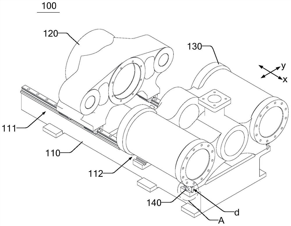
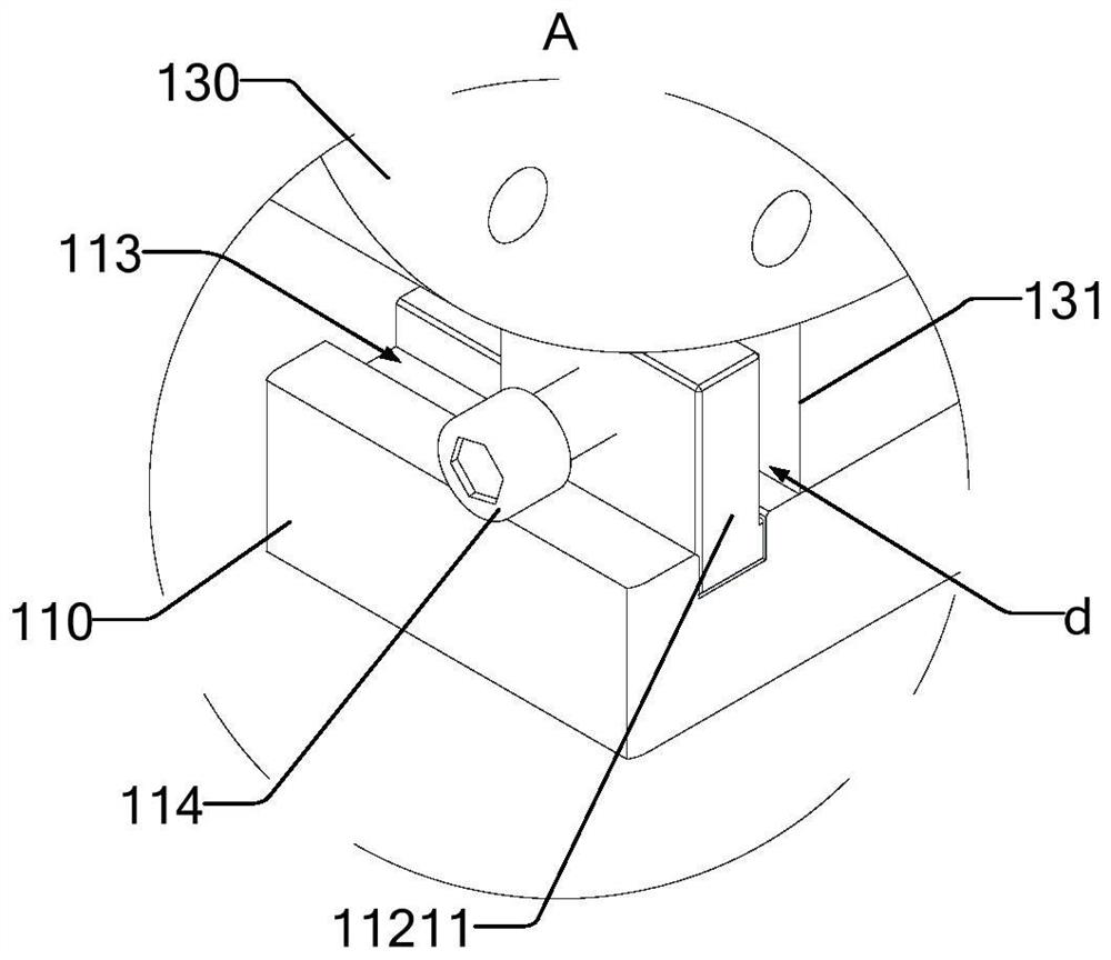
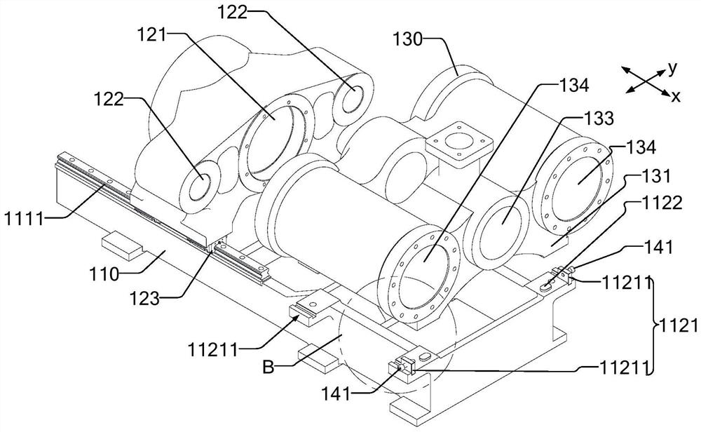
[0079] like Figure 1 to Figure 8 As shown, this embodiment proposes a glue injection mechanism 100 , including a base 110 , a glue injection tail plate 120 , a glue injection head plate 130 and an adjustment structure 140 .

[0080] Two injection oil cylinders are arranged on the injection head plate 130, and the specifications of the two injection oil cylinders are consistent and symmetrical to each other. The injection head plate 130 and the base 110 are fixed by screws. The base 110 is equipped with a linear slide rail 1111. The injection tail plate 120 is provided with a sliding part 123 and is slidably connected to the linear slide rail 1111 through the sliding part 123. The injection tail plate 120 is movable on the base 110 .

[0081] The glue injection tail plate 120 is connected with the piston rod of the glue injection cylinder by a nut, and the piston rod of the glue injection cylinder and the piston of the glue injection cylinder are connected by threads. The two ...


PUM


Abstract

The invention provides a glue injection mechanism and an injection molding machine, and the glue injection mechanism comprises a base which is provided with a first mounting position and a second mounting position which are arranged at an interval along a first direction; the glue injection tail plate is arranged at the first mounting position; the glue injection head plate is arranged at the second mounting position, a gap is formed between the glue injection head plate and the second mounting position in a second direction, and the second direction is inclined or perpendicular to the first direction; and the adjusting structure is arranged at the second mounting position and is configured to be matched with the injection head plate so as to adjust the position of the injection head plate in the second direction. The gap between the glue injection head plate and the second mounting position in the second direction provides a moving space for the glue injection head plate on the second mounting position, so that the position of the glue injection head plate on the base can be adjusted, and the relative position between the glue injection head plate and the glue injection tail plate can be adjusted. The adjusting structure acts on the glue injection head plate to adjust the relative position between the glue injection head plate and the glue injection tail plate, so that the relative position of the glue injection head plate and the glue injection tail plate meets the assembly requirement.

Description

technical field [0001] The invention relates to the field of injection molding, in particular to a glue injection mechanism and an injection molding machine. Background technique [0002] In the existing injection molding machine, when assembling the injection tail plate and the injection head plate, there are problems of insufficient installation and low installation position accuracy, resulting in positional deviation between the two, which easily leads to injection molding that needs to be assembled on it. The driving parts, injection parts and other parts of the machine cannot be installed, or even if they are barely installed, they will be damaged during the work process. Contents of the invention [0003] One object of the present invention is to provide a glue injection mechanism and an injection molding machine, which can fine-tune the installation position of the glue injection head plate through the adjustment structure, so as to ensure the position accuracy betw...

Claims


Application Information

Patent Timeline
IPC IPC(8): B29C45/53B29C45/17
CPCB29C45/53B29C45/531B29C45/1773Y02E60/10
Inventor 陈创鑫刘立雄梁健民
Owner 佛山市顺德区震德塑料机械有限公司
Learn More