
A kind of rowing machine button test equipment and test method

A technology of testing equipment and rowing machines, which is applied in the testing of mechanical components, testing of machine/structural components, testing of circuit breakers, etc. It can solve the problems of poor testing accuracy, high cost, and reduced testing efficiency, and improve testing accuracy , Improve test efficiency and save test cost

Active Publication Date: 2022-07-05
BOJIE ELECTROMECHANICAL SHANGHAI
View PDF0 Cites 0 Cited by
  • Summary
  • Abstract
  • Description
  • Claims
  • Application Information

AI Technical Summary

Problems solved by technology

[0005] In order to solve the problem of high cost, low test efficiency and poor test accuracy of the existing rowing machine button testing equipment, the application provides a rowing machine button testing equipment and testing method

Method used


Image

  • A kind of rowing machine button test equipment and test method
  • A kind of rowing machine button test equipment and test method
  • A kind of rowing machine button test equipment and test method

Examples


Embodiment 1

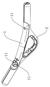
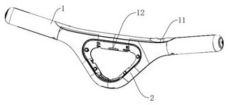
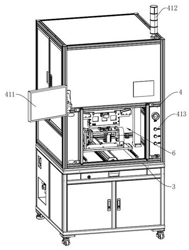
[0062] The embodiment of the present application discloses a device for testing the keys of a rowing machine. refer to Figure 1-6 , a rowing machine key test equipment, including a test machine 3, a PLC controller 4, a test assembly 5 for testing the control keys 11, and a multi-axis flip fixing assembly 6 for fixing the flip test piece. The PLC controller 4 , the test assembly 5 and the turning and fixing assembly 6 are all fixedly installed on the testing machine 3 , and the testing assembly 5 and the turning and fixing assembly 6 are all connected to the PLC controller 4 . The PLC controller 4 is connected with a peripheral component 41 , and the peripheral component 41 is fixedly installed on the testing machine 3 . The testing assembly 5 includes an X-axis module 51 that moves laterally along the testing machine 3 , a Z-axis module 52 that moves along the height direction of the testing machine 3 , and a testing component 53 for performing pressure testing on the keys. ...

Embodiment 2

[0085] refer to Figure 10-12 The difference between this embodiment and the first embodiment is that the test component 53 further includes a water source 533 , a water spray pipe 534 , a micro atomizing pump 535 and a current sensor 536 . The water source 533 is connected to the water inlet of the micro atomizing pump 535 , and the water spray pipe 534 is connected to the water outlet of the micro atomizing pump 535 . One end of the water spray pipe 534 is disposed toward the test probe column 531 and is fixedly connected with the atomizing spray head 537 . The detection end of the current sensor 536 is connected to the outer surface of the test probe post 531 . Through the settings of the water source 533 , the water spray pipe 534 , the micro atomizing pump 535 and the current sensor 536 , it is possible to simulate the use situation of the user operating the keys with wet hands during the key press test, and to detect whether the test piece will leak electricity during u...


PUM


Abstract

The present application relates to a rowing machine button test equipment and a test method. The test equipment includes a test machine, a PLC controller, a test assembly for testing control buttons, and a multi-axis flip-fixing assembly for fixing a flip test piece. The test assembly The PLC controller is connected with the PLC controller; the peripheral components are connected with the peripheral components, and the peripheral components are fixedly installed on the test machine; the test components include an X-axis module that moves laterally along the test machine, A Z-axis module that moves in the direction and a test part used to perform pressure testing on the keys; the flip-fixing assembly includes a Y-axis module that moves longitudinally along the test machine, and is installed on the Y-axis module to flip the test piece so that the control key to be tested is in the The flipping platform of the horizontal test position and the fixing parts installed on the flipping platform for fixing and supporting the test piece. The present application has the effects of saving test costs and effectively improving test efficiency and test accuracy.

Description

technical field [0001] The present application relates to the field of fitness equipment testing, and in particular, to a rowing machine button testing device and a testing method. Background technique [0002] Fitness equipment is often divided into two categories: single-function and comprehensive multi-function according to the number of training functions. Rowing machine is also known as rowing machine, rowing machine, rowing machine, rowing machine, dynamometer, land rowing machine, indoor rowing machine. The rowing machine has a good effect on the muscle strengthening of the legs, waist, upper limbs, chest and back. Each stroke, the upper limbs, lower limbs, waist and abdomen, and back will complete a complete contraction and extension in the process, which can achieve a full-body muscle aerobic exercise effect. Especially for people with more fat in the waist, abdomen and upper arms, the effect of rowing exercise is stronger. [0003] An existing rowing machine gri...

Claims


Application Information

Patent Timeline
Patent Type & Authority Patents(China)
IPC IPC(8): G01R31/327G01R1/04G01M13/00G05B19/05A63B22/00
CPCG01R31/3277G01R31/008G01R1/0408G01M13/00G05B19/05A63B22/0076
Inventor 程运宝张峰费杰陈晨
Owner BOJIE ELECTROMECHANICAL SHANGHAI
Learn More