Near source region frequency domain electromagnetic detection method and device, electronic equipment and storage medium
An electromagnetic detection and frequency domain technology, applied in the field of geophysical exploration, can solve problems such as unavailability, difficulty in extracting terrestrial electrical information, near-region electromagnetic field does not have plane wave properties, etc., to shorten the sending and receiving distance and improve the effect of formation resolution
- Summary
- Abstract
- Description
- Claims
- Application Information
AI Technical Summary
Problems solved by technology
Method used
Image

Examples
Embodiment 1
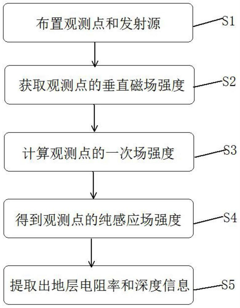
[0044] Such as figure 1 As shown, the present invention provides a method for electromagnetic detection in the frequency domain of the near-source region, comprising:
[0045] Step S1, arranging the emission source of the observation point;
[0046] Step S2, obtaining the total vertical magnetic field strength of the observation point;
[0047] Step S3, according to the length of the emission source, the emission current and the coordinates of the observation point, obtain the primary vertical magnetic field intensity generated by the emission source at the observation point;
[0048] Step S4, using the total vertical magnetic field strength to subtract a vertical magnetic field strength to obtain the purely induced vertical magnetic field strength at the observation point;
[0049] Step S5, using the inversion technique to extract formation resistivity and depth information from the purely induced vertical magnetic field strength.
[0050] As an implementation manner of th...
Embodiment 2
[0068] The present invention also provides an electromagnetic detection device in the frequency domain near the source region, including:
[0069] Obtaining module, is used for obtaining the vertical magnetic field intensity of observation point;
[0070] The first calculation module is used to obtain the primary field intensity generated by the emission source at the observation point according to the length of the emission source, the emission current and the coordinates of the observation point;
[0071] The second calculation module is used to subtract the primary field strength from the vertical magnetic field strength to obtain the pure induction field strength at the observation point;
[0072] The inversion module is used to extract the formation resistivity and depth information from the pure induction field strength by using inversion technology.
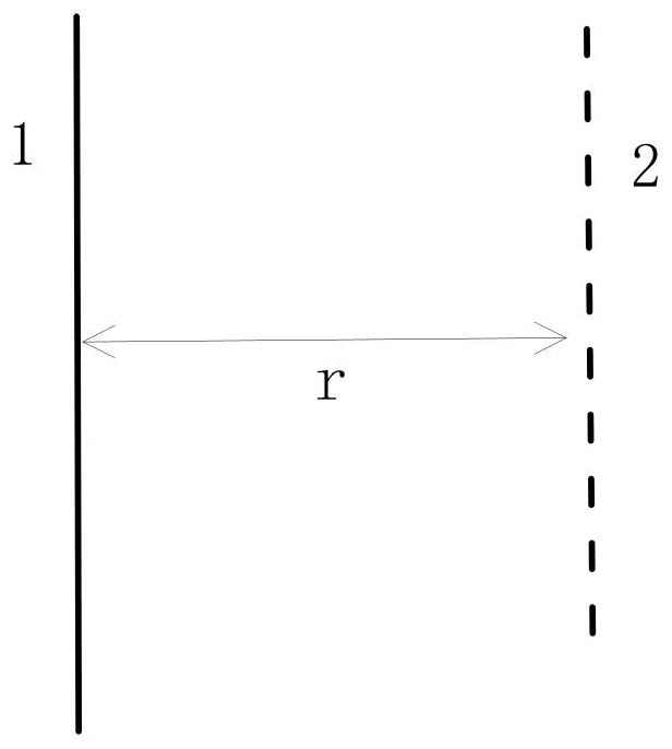
[0073] As an implementation manner of this embodiment, the distance between the observation point and the emission sour...
Embodiment 3
[0078] An embodiment of the present invention provides an electronic device, specifically, the electronic device includes a processor and a storage device; a computer program is stored on the storage device, and when the computer program is run by the processor, it performs electromagnetic detection in the near-source region frequency domain method.
[0079] The present invention also provides a storage medium, the storage medium stores machine-executable instructions, and when the machine-executable instructions are invoked and executed by a processor, the machine-executable instructions cause the processor to realize the near-source region Frequency domain electromagnetic detection method.
PUM
 Abstract
Description
Claims
Application Information
 - Generate Ideas
- Intellectual Property
- Life Sciences
- Materials
- Tech Scout
- Unparalleled Data Quality
- Higher Quality Content
- 60% Fewer Hallucinations
Browse by: Latest US Patents, China's latest patents, Technical Efficacy Thesaurus, Application Domain, Technology Topic, Popular Technical Reports.
© 2025 PatSnap. All rights reserved.Legal|Privacy policy|Modern Slavery Act Transparency Statement|Sitemap|About US| Contact US: help@patsnap.com