
Automatic molding equipment for internal combustion engine accessories

A technology for internal combustion engines and accessories, which is applied in the field of automatic molding equipment for internal combustion engine accessories, and can solve problems such as limited sand filling range, different sand content, and poor molding effects

Pending Publication Date: 2022-05-24
江西樟树市福铃内燃机配件有限公司
View PDF7 Cites 0 Cited by
  • Summary
  • Abstract
  • Description
  • Claims
  • Application Information

AI Technical Summary

Problems solved by technology

[0004] In view of this, the main purpose of the present invention is to solve the technical problem that the sand content in each part of the mold is different due to the limited range of sand filling, resulting in poor molding effect

Method used


Image

  • Automatic molding equipment for internal combustion engine accessories
  • Automatic molding equipment for internal combustion engine accessories

Examples


Embodiment Construction

[0018] The present application will be further described in detail below with reference to the accompanying drawings and embodiments. It should be understood that the specific embodiments described herein are only used to explain the related invention, but not to limit the invention. In addition, it should be noted that, for the convenience of description, only the parts related to the related invention are shown in the drawings. It should be noted that the embodiments in the present application and the features of the embodiments may be combined with each other in the case of no conflict. The present application will be described in detail below with reference to the accompanying drawings and in conjunction with the embodiments.

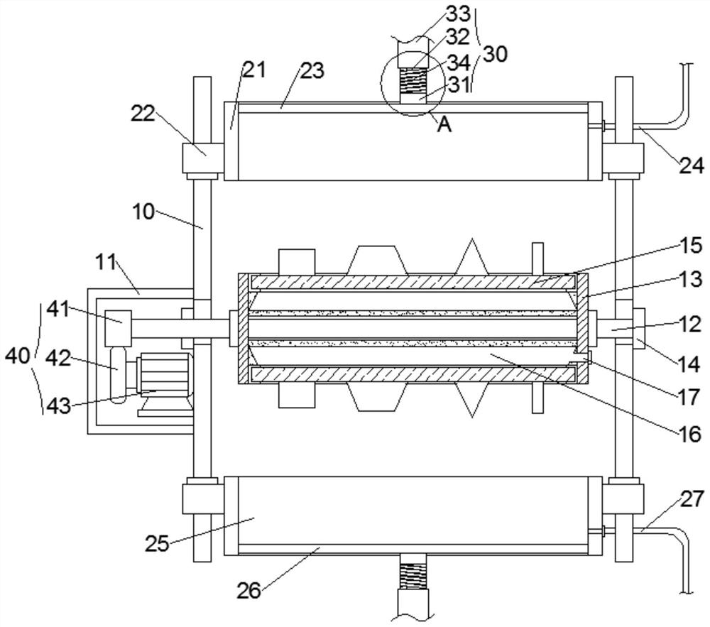
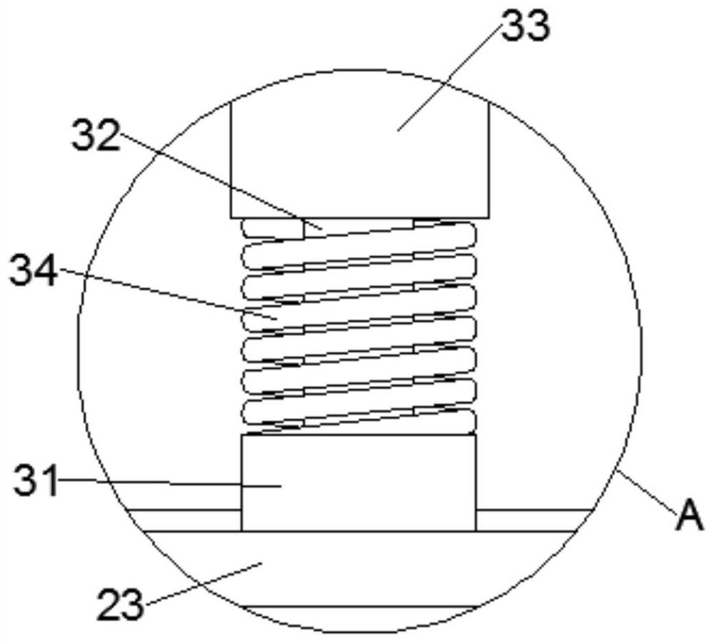
[0019] see Figure 1-Figure 2 , which shows an automatic molding equipment for internal combustion engine parts of the present application, including a guide rod column 10 , a middle mold frame 13 , an upper mold frame 21 , a lower mold frame 25 a...


PUM


Abstract

The invention provides automatic molding equipment for internal combustion engine accessories. The automatic molding equipment comprises a guide rod stand column, a middle mold frame, an upper mold frame, a lower mold frame and a vibration assembly arranged on the guide rod stand column. A supporting guide rod is movably arranged in the middle of the guide rod stand column, a middle mold frame is fixedly connected to the supporting guide rod, and a middle transverse plate is arranged on the middle mold frame. The upper mold frame and the lower mold frame are movably connected with the guide rod stand columns through sliding blocks arranged on the guide rod stand columns in a sleeving mode respectively, an upper pressing plate and a lower pressing plate are movably arranged in the upper mold frame and the lower mold frame respectively, and the end faces, away from the middle mold frame, of the upper pressing plate and the lower pressing plate are connected with a driving source through a buffering mechanism. The vibration assembly comprises a transmission block arranged on the supporting guide rod, a driving motor fixed to the guide rod stand column and a special-shaped block coaxially connected with the output end of the driving motor. The technical problem that due to the fact that the sand filling range is limited, the sand contents of all parts in the middle mold frame are different, and the forming effect is poor is solved.

Description

technical field [0001] The invention relates to the field of casting equipment, in particular to an automatic molding equipment for internal combustion engine parts. Background technique [0002] The molding machine is a casting equipment used to make sand molds. Its main functions are: filling sand, filling the loose molding sand into the sand box; The loose molding sand in the sand box is compacted, so that the sand mold has the necessary strength in the process of handling and pouring. [0003] The existing molding machine is carrying out sand filling and compaction work, and because the sand filling range is limited, the sand content of each part of the mold is different, resulting in poor molding effect. SUMMARY OF THE INVENTION [0004] In view of this, the main purpose of the present invention is to solve the technical problem that the sand content is different in each part of the mold due to the limited sand filling range, resulting in poor molding effect. [000...

Claims


Application Information

Patent Timeline
Patent Type & Authority Applications(China)
IPC IPC(8): B22C15/28
CPCB22C15/28
Inventor 李羽陈涛魏端华黄建民
Owner 江西樟树市福铃内燃机配件有限公司
Learn More