Plate conveying equipment and method based on visual monitoring and intelligent grabbing

A technology for visual monitoring and conveying equipment, applied in the field of sheet metal processing, can solve problems such as difficulty in adapting to sheets and different shapes

Pending Publication Date: 2022-05-24
厦门莱蔓新材料科技有限公司
View PDF0 Cites 0 Cited by
  • Summary
  • Abstract
  • Description
  • Claims
  • Application Information

AI Technical Summary

Problems solved by technology

[0003] When moving the sheet between different stamping equipment, since the shape of the remaining sheet will be different after different nesting processes are completed, it is difficult to adapt to different shapes of sheets through ordinary suction cups

Method used


Image

  • Plate conveying equipment and method based on visual monitoring and intelligent grabbing
  • Plate conveying equipment and method based on visual monitoring and intelligent grabbing
  • Plate conveying equipment and method based on visual monitoring and intelligent grabbing

Examples


Embodiment 1

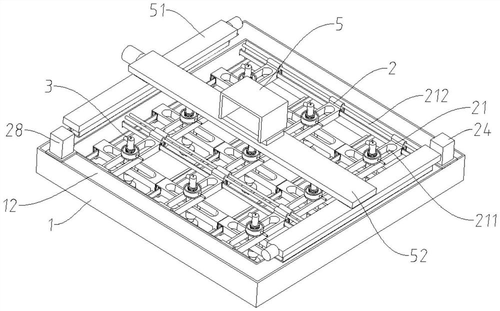
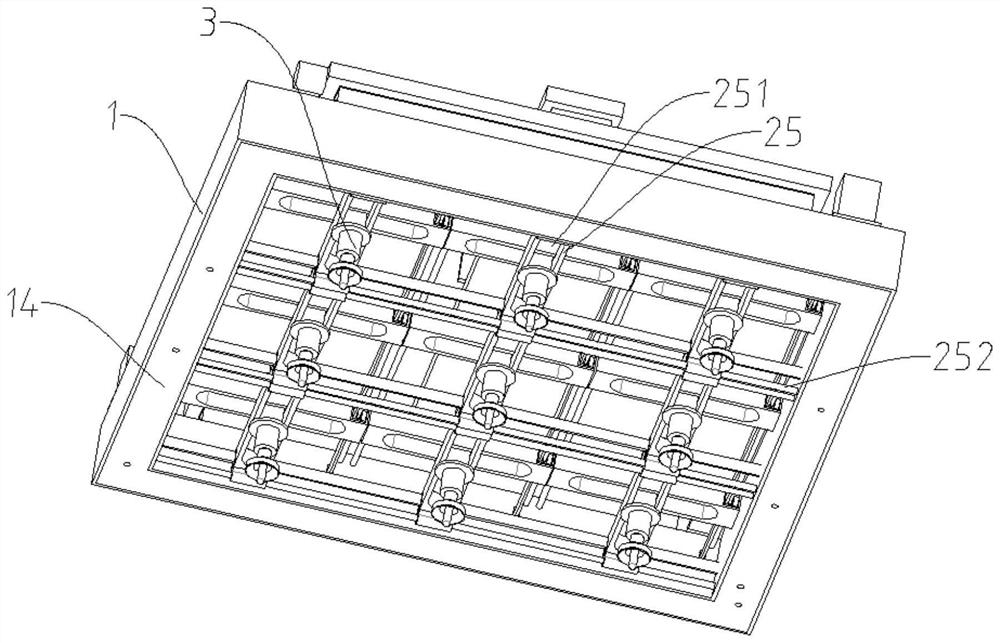
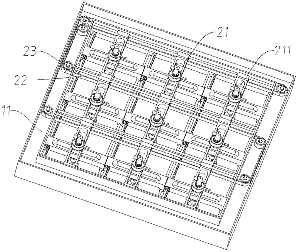
[0050] like Figure 1-8As shown, a plate conveying device based on visual monitoring and intelligent grasping includes an installation frame 1 and a plurality of suction cup assemblies 3 mounted on the installation frame 1, and the plurality of suction cup assemblies 3 can move relative to the installation frame 1 and different suction cup assemblies 3 The movements of the suction cups are independent of each other, the suction cup assembly 3 can be moved to the required position to suck up the board, and the suction cup assembly 3 is driven by the drive assembly 2 .

[0051] The suction cup assembly 3 includes a suction cup 31 , an air guide cylinder 32 , and an installation cylinder 33 . The working end of the suction cup 31 faces downwards. The upper end of the air guide cylinder 32 is communicated with the negative pressure device through a pipeline, so as to realize the adsorption of the plate. The installation cylinder 33 is sleeved on the air guide cylinder 32 and the ...

Embodiment 2

[0070] This embodiment is the use method of the first embodiment, which specifically includes the following steps:

[0071] Step 1: the plate conveying equipment is moved to the top of the plate;

[0072] Step 2: the camera 310 of each suction cup assembly 3 takes a picture of the plate, and judges whether there is a plate that can be sucked up directly below each suction cup assembly 3 according to the photographed picture;

[0073] Step 3: If there is a plate that can be sucked up directly under each suction cup assembly 3, the plate conveying device moves downward until all the suction cup assemblies 3 suck the plate;

[0074] Step 4: Move the plate conveying equipment to move the plate to the required position.

[0075] When performing step 3, if there is no sheet for suction directly below part of the suction cup assembly 3, perform the following steps:

[0076] Step 3.1: According to the photographed pictures, determine whether the suction cup assembly 3 without the plat...


PUM


Abstract

The invention provides plate conveying equipment based on visual monitoring and intelligent grabbing. The plate conveying equipment comprises a mounting frame; the multiple suction cup assemblies are used for sucking up the plates and installed on the installation frame through a driving assembly, the driving assembly can drive the suction cup assemblies to move in the plane where the installation frame is located relative to the installation frame, and each suction cup assembly can independently move relative to the installation frame; the suction cup assembly comprises a suction cup with a downward suction end; the lower end of the air guide cylinder is communicated with the upper end of the suction cup; the connecting cylinder is arranged at the upper end of the air guide cylinder and is coaxial with the air guide cylinder, the upper end of the connecting cylinder is blocked, the lower end of the connecting cylinder is opened, and an air inlet is formed in the connecting cylinder and is communicated with the negative pressure device through a pipeline; and the mounting cylinder sleeves the air guide cylinder, is coaxially arranged with the air guide cylinder and is connected to the driving assembly. The jacking device is suitable for moving the plates subjected to jacking processing.

Description

technical field [0001] The invention relates to the field of sheet metal processing, in particular to a sheet conveying device and method for intelligently grasping based on visual monitoring. Background technique [0002] In sheet metal processing, in order to save materials, nesting is often required. Taking stamping as an example, after stamping one material, the remaining sheet can also stamp another material, so that the sheet can be more fully utilized. [0003] When the sheet is moved between different stamping equipment, since the shape of the remaining sheet will be different after the completion of different nesting processing, it is difficult to adapt to the sheet of different shapes by ordinary suction cups. SUMMARY OF THE INVENTION [0004] The main purpose of the present invention is to provide a plate conveying device and method for intelligent grasping based on visual monitoring. [0005] In order to achieve the above purpose, the technical solution adop...

Claims


Application Information

Patent Timeline
Patent Type & Authority Applications(China)
IPC IPC(8): B65G47/91G01L5/00G01V8/10
CPCB65G47/912G01V8/10G01L5/0028
Inventor 梁树海
Owner 厦门莱蔓新材料科技有限公司
Why Eureka
Try Eureka