Portable Fluid Delivery Systems & Kits

A fluid delivery system and fluid delivery technology, applied in fluid treatment accessories, fluid treatment, fluid transfer, etc., can solve problems such as the impact of lifting thrust, and achieve the effects of less energy consumption, easy portability, and small size

Inactive Publication Date: 2015-08-19
GREEN HYDROTEC
View PDF3 Cites 0 Cited by
  • Summary
  • Abstract
  • Description
  • Claims
  • Application Information

AI Technical Summary

Problems solved by technology

However, the lifting thrust of the capillary phenomenon is related to the specific gravity, surface tension and temperature of the liquid. Faced with different liquids to be transported and different delivery environments, the lifting thrust will be affected, and when the pressure resistance at the downstream end is high , such as 0.5 atmospheric pressure or 1 atmospheric pressure or even higher pressure, it is difficult to meet the demand simply by using capillary lifting force to transport liquid

Method used


Image

  • Portable Fluid Delivery Systems & Kits
  • Portable Fluid Delivery Systems & Kits
  • Portable Fluid Delivery Systems & Kits

Examples


Embodiment Construction

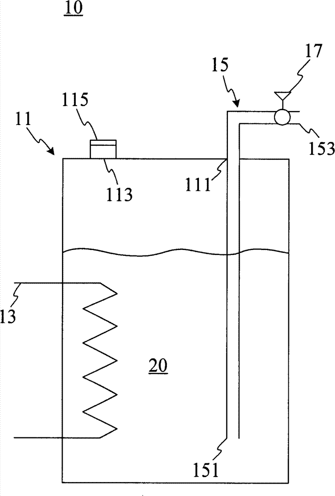
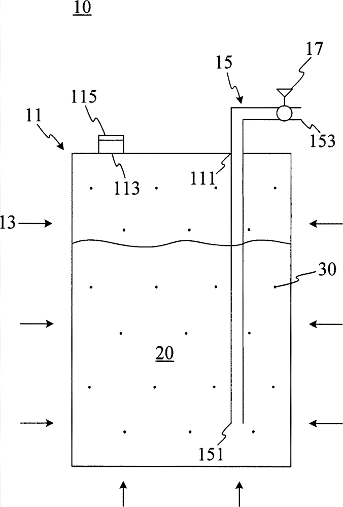
[0015] A preferred embodiment of the present invention is figure 1 As shown, the fluid delivery system 10 includes a container 11 , a heat source 13 , and a delivery line 15 . Wherein, the container 11 has a discharge hole 111 and an accommodating space, and preferably must withstand pressure, and the degree of pressure resistance depends on operating conditions (including operating temperature, fluid type, etc.). The accommodating space is for accommodating a liquid to be transported 20 which is liquid at normal temperature, and the transport pipeline 15 is connected to the discharge hole 111 . When the fluid delivery system 10 is in operation, except the delivery pipeline 15 becomes an external channel, the container 11 is in a closed state substantially, and part of the fluid 20 to be delivered is discharged from the fluid delivery system through the discharge hole 111 along the delivery pipeline 15 10 outside.

[0016] More specifically, the delivery pipeline 15 may incl...


PUM


Abstract

A portable fluid delivering system comprising a container, a heat source, a flow rate regulating device and a delivery tube is provided. The container has a containing space for a fluid to be delivered, in a liquid state at room temperature. The heat source provides an elevated vapor pressure in the containing space over the fluid to be delivered, whereby the fluid to be delivered is driven at a desirable rate along the delivery tube.

Description

technical field [0001] The present invention relates to a fluid delivery system and kit; in particular, a portable fluid delivery system and kit suitable for transporting microfluids, which can be used in the application of tiny devices such as fuel cells to provide raw materials needed for battery operation . Background technique [0002] In industry (such as: chemical industry), there is often a demand for liquid transportation. Generally speaking, the mechanical compression of the pump is usually used as the pressure source for the transportation of liquid, which is connected to the upstream end of the liquid transportation pipeline. By increasing the upstream The pressure in the line drives the fluid to the lower pressure end of the line (downstream). Since the increase in pressure comes from a mechanical compression pump, the overall system is bulky and consumes more energy. [0003] However, with the advancement of science and technology, various application devices ...

Claims


Application Information

Patent Timeline
Patent Type & Authority Patents(China)
IPC IPC(8): H01M8/04F17D1/12
CPCY02E60/50F17C2223/033F17C2221/033H01M8/0631F17C2221/011F17C2250/0443Y02E60/321H01M8/04268H01M8/04022F17C2270/0763F17C2227/0309F17C2221/012F17C2223/047H01M8/04216F17C2270/0184F17C2227/0332F17C2223/0161F17C2227/0107F17C2227/0327H01M8/04208F17C2205/0323F17C2260/036F17C2227/0304F17C5/02F17C2250/0439Y02E60/32
Inventor 叶冠廷汪杭甫洪嘉业雷敏宏
Owner GREEN HYDROTEC
Why Eureka
Try Eureka