Vacuum gear pump

A gear pump and vacuum technology, applied in the direction of pumps, rotary piston pumps, rotary piston machines, etc., can solve the problems of insufficient oil absorption, cavitation, oil suction, etc., and achieve simple structure, convenient cleaning, disassembly and installation convenient effect

Inactive Publication Date: 2015-11-25
邱称平
View PDF4 Cites 0 Cited by
  • Summary
  • Abstract
  • Description
  • Claims
  • Application Information

AI Technical Summary

Problems solved by technology

[0003] However, the pumps in the prior art generally cannot be used to transport liquids with high viscosity and high suction lift, or liquids with negative pressure, because they are prone to insufficient oil absorption or no oil absorption, and cavitation phenomenon

Method used


Image

  • Vacuum gear pump
  • Vacuum gear pump
  • Vacuum gear pump

Examples


Embodiment Construction

[0028] The present invention will be described in further detail below in conjunction with the examples and the accompanying drawings, but the implementation of the present invention is not limited thereto.

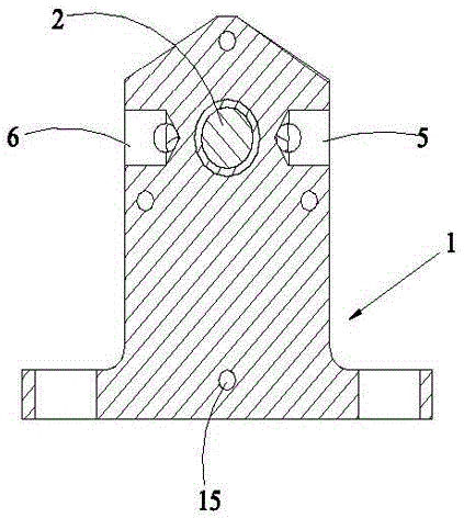
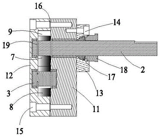
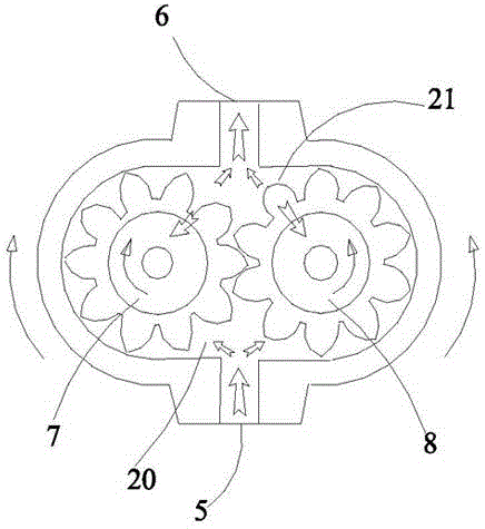
[0029] like figure 1 and 2 As shown, the vacuum gear pump provided by the present invention includes a pump body 1, a first main shaft 2, a second main shaft 3, a liquid inlet 5, a liquid outlet 6, and a first gear 7 and a second gear 8 meshing with each other, The inside of the pump body 1 is provided with an inner cavity 9, the first gear 7 and the second gear 8 are arranged in the inner cavity 9, and the liquid inlet 5 and the liquid outlet 6 are connected with the inner cavity 9, the first main shaft 2 and the The second main shaft 3 passes through the first gear 8 and the second gear 9 respectively, and the second main shaft 3 is located in the pump body 1 , and one end of the first main shaft 2 protrudes from the inside of the pump body 1 .

[0030] Wherein, the p...


PUM


Abstract

The invention belongs to the technical field of gear pumps, and particularly relates to a vacuum gear pump. The vacuum gear pump comprises a pump body, a first main shaft, a second main shaft, a liquid inlet, a liquid outlet, a first gear and a second gear. The first gear and the second gear are meshed with each other. An inner cavity is formed in the pump body. The first gear and the second gear are both arranged in the inner cavity. The liquid inlet and the liquid outlet are both communicated with the inner cavity. The first main shaft and the second main shaft are arranged in the first gear and the second gear in a penetrating manner respectively. The second main shaft is located in the pump body. One end of the first main shaft extends out of the inner portion of the pump body. Compared with the prior art, when the first gear and the second gear which are meshed with each other are gradually separated, the sealing working volume is greatly increased, a liquid suction cavity which is partially vacuum is formed, and liquid is sucked into the liquid suction cavity under the effect of external atmosphere pressure and is brought into a high-pressure cavity. Pressure liquid in the high-pressure cavity acts on the first gear and the second gear, and therefore the volume in the high-pressure cavity can be decreased, and liquid can be output from the liquid outlet.

Description

technical field [0001] The invention belongs to the technical field of gear pumps, in particular to a vacuum gear pump. Background technique [0002] A pump is a machine that transports liquid or pressurizes the liquid. It transfers the mechanical energy of the prime mover or other external energy to the liquid to increase the energy of the liquid. Pumps can usually be divided into three categories according to their working principles: positive displacement pumps, dynamic pumps and other types of pumps. Among them, the positive displacement pump relies on the movement of the working parts to periodically increase and decrease the working volume to absorb and discharge the liquid, and directly increases the pressure of the liquid by the extrusion of the working parts. According to the different structures of the moving parts, the positive displacement pump It can be divided into piston pump, plunger pump, screw pump, vane pump and water ring pump. [0003] However, the pum...

Claims


Application Information

Patent Timeline
Patent Type & Authority Applications(China)
IPC IPC(8): F04C2/18F04C13/00
Inventor 邱称平
Owner 邱称平
Why Eureka
Try Eureka