Combustion chamber and diesel engine

A combustion chamber and pit technology, which is applied in the field of combustion chamber and diesel engine, can solve the problems of aggravating the wear of piston and cylinder liner, increasing the wear of piston ring and cylinder liner, burning engine oil, etc., so as to improve the uniformity of oil and gas mixing and strengthen the The effect of entrainment effect

Inactive Publication Date: 2022-05-24
WEICHAI POWER CO LTD
View PDF9 Cites 0 Cited by
  • Summary
  • Abstract
  • Description
  • Claims
  • Application Information

AI Technical Summary

Problems solved by technology

Among them, the upwardly flowing oil bundle flows along the smooth transition surface 03, which limits the air utilization rate in the outer edge area of ​​the combustion chamber pit, resulting in poor oil-gas mixing effect in the outer edge area, high heat transfer loss, and the oil beam It will further move along the upper top surface 04 of the piston to a position close to the cylinder liner for combustion, which will easily cause defects in burning engine oil and increase the wear of the piston ring and cylinder liner
In the prior art, in order to further improve the air utilization rate of the outer edge area of ​​

Method used


Image

  • Combustion chamber and diesel engine
  • Combustion chamber and diesel engine
  • Combustion chamber and diesel engine

Examples


Embodiment Construction

[0047]The following will be combined with the accompanying drawings in the embodiments of the present invention, the technical solution in the embodiments of the present invention will be described clearly and completely, it is clear that the embodiments described are only a part of the embodiment of the present invention, not all embodiments. Based on embodiments in the present invention, all other embodiments obtained by those of ordinary skill in the art without making creative work, are within the scope of protection of the present invention.

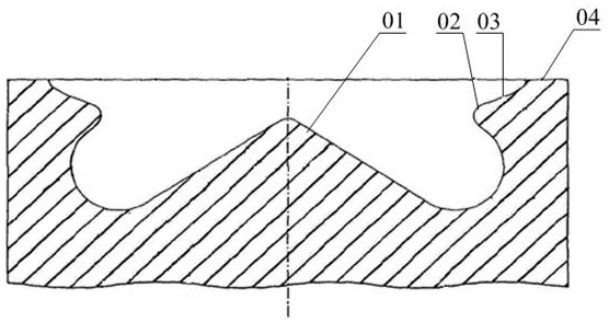
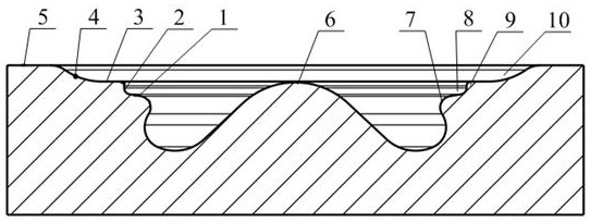
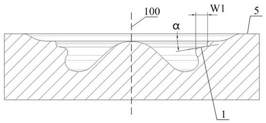
[0048] Please refer to Figures 2 through 21 , the present invention provides a combustion chamber, comprising a combustion chamber pit located at the top of the piston, the circumferential wall of the combustion chamber pit is provided with a circular flange 7 protruding in the direction of the injector, the annular flange 7 is located below the top surface of the piston 5 and closer to the centerline of the pit 100 than the upper edge ...


PUM


Abstract

According to the combustion chamber, an annular flange protruding in the direction of an oil nozzle is arranged on the circumferential wall face of a combustion chamber pit, and the annular flange is located below the upper top face of a piston and is closer to the center line of the pit than the upper edge of the combustion chamber pit. The edge of the protruding top end of the annular flange is connected with the upper edge of the combustion chamber pit through a pit transition face, and the pit transition face comprises first to fourth flow guide faces which are sequentially connected from inside to outside in the radial direction of the combustion chamber pit and gradually get close to the upper top face of the piston. The second flow guide face and the third flow guide face form an annular boss protruding towards the bottom face of the air cylinder cover, the first flow guide face and the second flow guide face form a first annular groove, and the third flow guide face and the fourth flow guide face form a second annular groove. According to the scheme, oil beams form jet flow through the annular boss, the oil-gas mixing uniformity in the combustion chamber is improved, meanwhile, an air interlayer is formed in the second annular groove, the heat transfer loss of the piston is reduced, and the engine efficiency is improved.

Description

Technical field [0001] The present invention relates to the field of engine technology, in particular to a combustion chamber and a diesel engine. Background [0002] Please refer to Figure 1 In order to make the oil beam in the combustion chamber of the diesel engine better mixed with the air, the existing diesel engine combustion chamber is usually included in the piston top design of the ω-type combustion chamber pit structure, specifically, the bottom center of the ω-type combustion chamber pit structure is designed with an upward projection of a roughly conical central convex structure 01, the circumferential side wall of the combustion chamber pit near the position of the top surface of the piston 04 is designed with a radial inwardly protruding annular flange structure 02. Diesel engine in the work, the fuel at a high pressure and high speed from the injector injection hole injection, in the cylinder air resistance and fuel in the high-speed flow of the internal disturbanc...

Claims


Application Information

Patent Timeline
IPC IPC(8): F02B23/06
CPCF02B23/0672F02B23/0621Y02T10/12
Inventor 崔京朋李小燕窦站成杜飞飞
Owner WEICHAI POWER CO LTD
Why Eureka
Try Eureka