Supercharge Your Innovation With Domain-Expert AI Agents!

Projection light source and projection equipment

A projection and light source technology, which is applied in optics, optical components, instruments, etc., can solve the problems of poor display effect of projected images, achieve good display effect, small aspect ratio, and improve laser utilization

Pending Publication Date: 2022-05-24
QINGDAO HISENSE LASER DISPLAY CO LTD
View PDF0 Cites 1 Cited by
  • Summary
  • Abstract
  • Description
  • Claims
  • Application Information

AI Technical Summary

Problems solved by technology

[0005] This application provides a projection light source and projection equipment, which can solve the problem of poor display effect of projection images

Method used


Image

  • Projection light source and projection equipment
  • Projection light source and projection equipment
  • Projection light source and projection equipment

Examples


Embodiment Construction

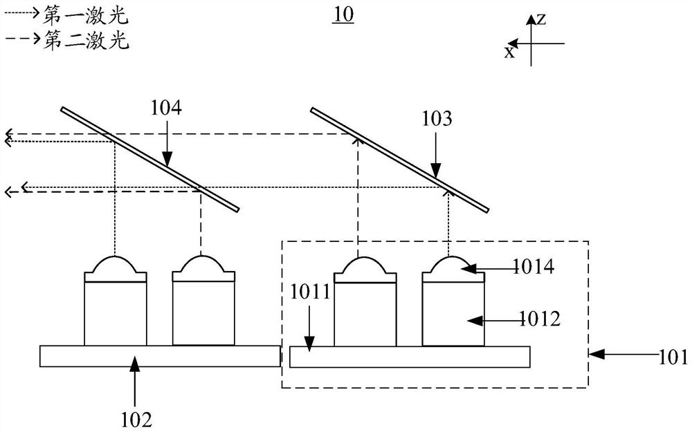
[0034] The first laser 101 and the second laser 102 can be sequentially arranged along the first direction, such as the first direction in the figure

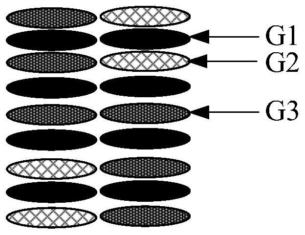
[0037] FIG. 3 is a schematic diagram of a light spot formed by a laser light emitted by a projection light source according to an embodiment of the present application.

[0045] In this optional manner, the mirror surfaces of the first light combining mirror 103 and the second light combining mirror 104 may be parallel to each other. This species can

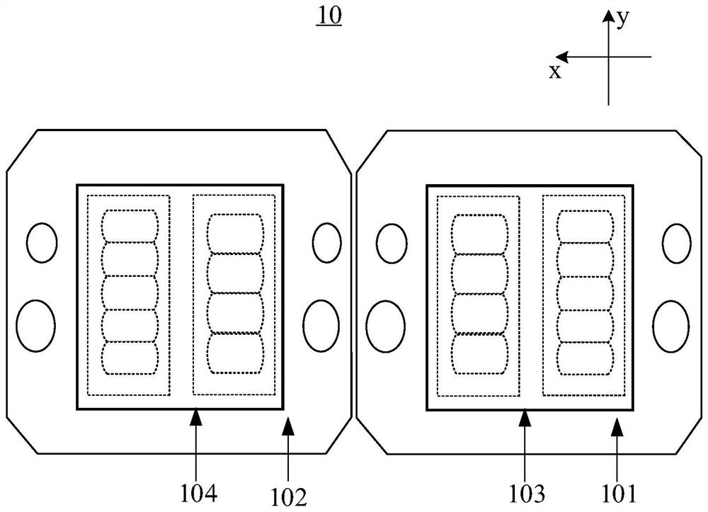
[0048] In this optional implementation, the arrangement directions of the emitting regions of different lasers in the laser can be flexibly set.

[0050] Optionally, the first light-combining mirror 103 and the second light-combining mirror 104 may be parallel, and both are arranged obliquely. The first combiner

[0051] The laser 101 in the projection light source 10 is described below with reference to the accompanying drawings. In the embodiment of the present application, the f...


PUM


Abstract

The invention discloses a projection light source and projection equipment, and belongs to the technical field of photoelectricity. In the projection light source, a first laser and a second laser are sequentially arranged along a first direction, and a first light combining mirror and a second light combining mirror are sequentially arranged along the first direction; in the first laser and the second laser, the emergent area of the first laser and the emergent area of the second laser are parallel to the first direction; laser emitted by the first laser device is emitted to the first light combining mirror, and the first light combining mirror is used for reflecting the incident laser to the second light combining mirror in the first direction; the laser emitted by the second laser device is emitted to the second light combining mirror, and the second light combining mirror is used for reflecting the laser emitted by the second laser device in the first direction and transmitting the laser emitted by the first light combining mirror in the first direction. The problem that the display effect of the projection picture formed based on the laser emitted by the projection light source is poor is solved. The invention is used for emitting light.

Description

Projection light source and projection equipment technical field [0001] The present application relates to the field of optoelectronic technology, in particular to a projection light source and projection equipment. Background technique [0002] With the development of optoelectronic technology, projection equipment is widely used, and the requirements for the display effect of the projection screen are also Higher and higher. [0003] The projection light source in the projection device can emit lasers of various colors, and then based on the laser projection to form a projection shadow screen. In the related art, the projection light source may include a laser and a light combining lens group, and the light combining lens group can emit the laser The lasers of different colors are mixed and emitted. The laser light can then be directed to the subsequent modulated optical path, based on the image to be projected The laser is modulated and then emitted, thereby reali...

Claims


Application Information

Patent Timeline
IPC IPC(8): G02B27/10G02B27/14G03B21/20
CPCG02B27/1006G02B27/14G03B21/2033G03B21/208
Inventor 李巍顾晓强田有良
Owner QINGDAO HISENSE LASER DISPLAY CO LTD
Features
  • R&D
  • Intellectual Property
  • Life Sciences
  • Materials
  • Tech Scout
  • Unparalleled Data Quality
  • Higher Quality Content
  • 60% Fewer Hallucinations
Learn More