
Plug and direct insertion type connector

A technology of plugs and connecting sleeves, which is applied in the direction of connection, two-part connection device, and parts of the connection device. It can solve the problems of heavy locking mechanism, inflexibility, and difficult operation, and achieve the effect of easy unlocking.

Pending Publication Date: 2022-05-27
SICHUAN HUAFENG ENTERPRISE GRP
View PDF4 Cites 0 Cited by
  • Summary
  • Abstract
  • Description
  • Claims
  • Application Information

AI Technical Summary

Problems solved by technology

At present, the locking mechanism of the in-line connector is relatively mechanical and has no flexibility. At the same time, because the locking mechanism involves the connection reliability of the connector, the locking mechanism is relatively heavy, the structure is complicated, and the operation is difficult.

Method used


Image

  • Plug and direct insertion type connector
  • Plug and direct insertion type connector
  • Plug and direct insertion type connector

Examples


Embodiment Construction

[0030] In order to make the purposes, technical solutions and advantages of the embodiments of the present invention clearer, the technical solutions in the embodiments of the present invention will be clearly and completely described below with reference to the accompanying drawings in the embodiments of the present invention. Obviously, the described embodiments It is a part of embodiment of this invention, and it is not an embodiment of all. The components of the embodiments of the invention generally described and illustrated in the drawings herein may be arranged and designed in a variety of different configurations.

[0031] Thus, the following detailed description of the embodiments of the invention provided in the accompanying drawings is not intended to limit the scope of the invention as claimed, but is merely representative of selected embodiments of the invention. Based on the embodiments of the present invention, all other embodiments obtained by those of ordinary...


PUM


Abstract

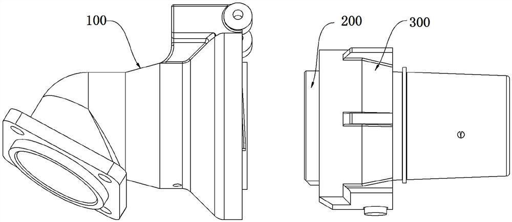
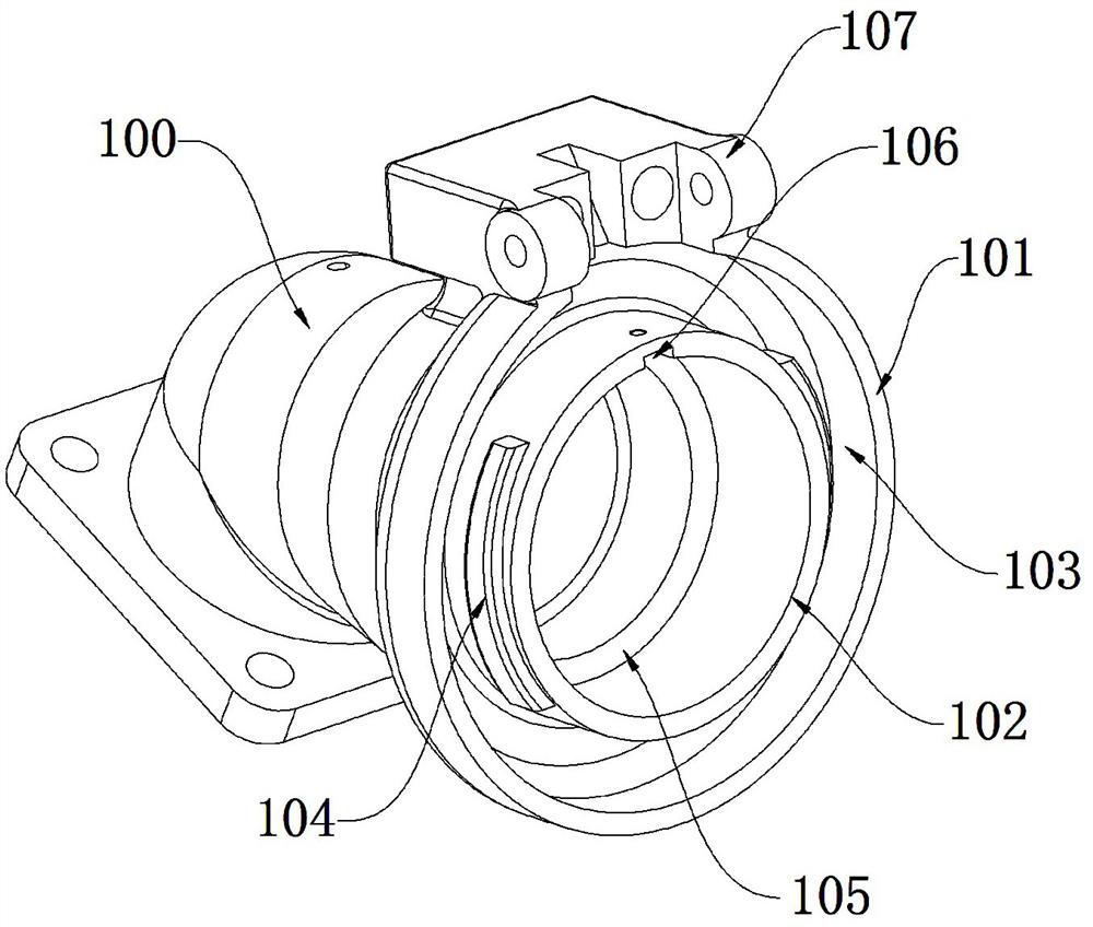
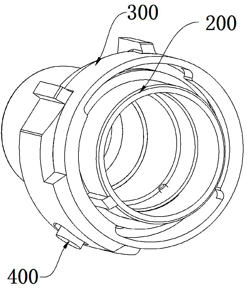
The plug comprises a head shell, a connecting sleeve and a ratchet mechanism, the ratchet mechanism comprises a lock hook and an arc-shaped rack, the arc-shaped rack is installed on the outer circumference of the head shell, the head shell is sleeved with the connecting sleeve, the connecting sleeve can push the head shell to move towards a base shell, the lock hook is installed on the connecting sleeve, and the lock hook is meshed with the arc-shaped rack. A convex rib a is arranged on the inner side wall of the connecting sleeve, the locking end face of the convex rib a is arranged along a spiral track, the direct insertion type connector comprises a socket and a plug, the socket and the plug are inserted, the socket comprises a socket shell, the insertion end of the socket shell is provided with an outer cylinder and an inner cylinder, the inner cylinder is located in the outer cylinder, a U-shaped cavity is formed between the inner cylinder and the outer cylinder, and the U-shaped cavity is communicated with the socket shell. A convex rib b is arranged on the outer side wall of the inner barrel, the locking end face of the convex rib b is arranged along a spiral track, and the spiral track of the convex rib b is matched with the spiral track of the convex rib a. The invention has the advantages of labor saving in insertion, reliable connection and convenience in unlocking.

Description

technical field [0001] The present invention relates to a connector, in particular to a plug and an in-line connector. Background technique [0002] In-line connectors are favored by the market because of their fast and convenient insertion and removal. The locking mechanism of the in-line connector is one of the most important components. The operation performance and safety performance of the locking mechanism are directly related to the performance of the in-line connector. At present, the locking mechanism of the in-line connector is relatively mechanical and has no flexibility. At the same time, because the locking mechanism is related to the connection reliability of the connector, the locking mechanism is heavy, complicated in structure and difficult to operate. SUMMARY OF THE INVENTION [0003] The purpose of the present invention is to overcome the shortcomings of the prior art, and to provide a plug and an in-line connector, which can ingeniously realize the loc...

Claims


Application Information

Patent Timeline
Patent Type & Authority Applications(China)
IPC IPC(8): H01R13/502H01R24/00H01R13/52H01R13/639
CPCH01R13/502H01R24/00H01R13/5202H01R13/639Y02T90/14
Inventor 蒋芳芳唐继
Owner SICHUAN HUAFENG ENTERPRISE GRP
Learn More