Modular wall system

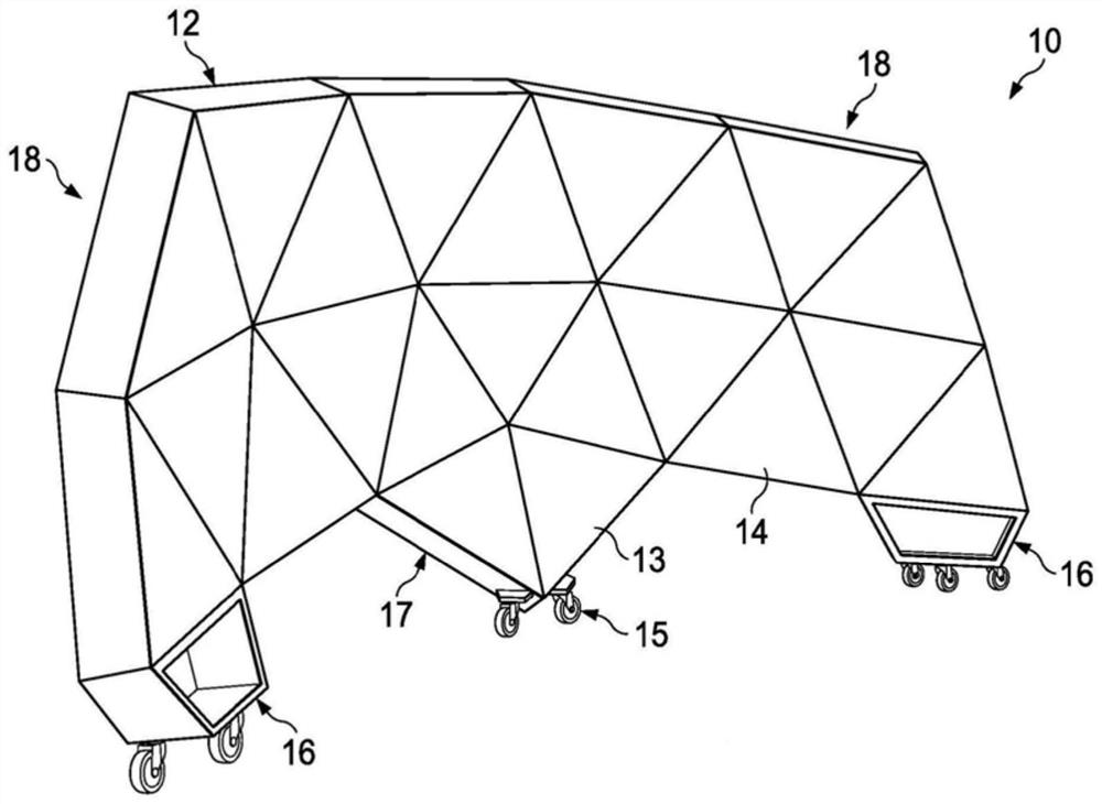
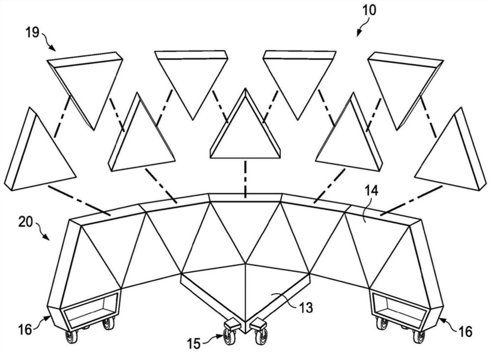
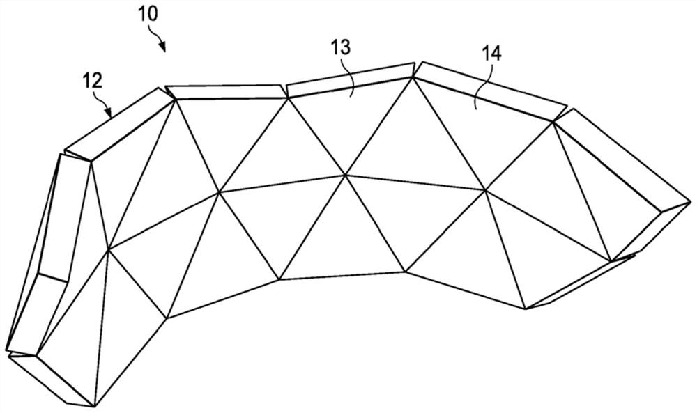
A modular, wall-structured technology that can be used in walls, buildings, screens, etc., to solve problems such as bulkiness, difficulty in hiding electrical wiring, overhauling or rewiring, large frames and partitions, etc.

Pending Publication Date: 2022-05-27
制造有限责任公司
View PDF6 Cites 0 Cited by
  • Summary
  • Abstract
  • Description
  • Claims
  • Application Information

AI Technical Summary

Problems solved by technology

This structure can be complex and therefore difficult to assemble and disassemble
Traditional frames and partitions can be large and bulky, and as such can be difficult to transport or move between rooms
In some cases, this legacy structure can make it difficult to conceal, repair or rewire electrical or data transmission wiring for telephones, computers or other common office equipment

Method used


Image

  • Modular wall system
  • Modular wall system
  • Modular wall system

Examples


Embodiment Construction

[0029] Various non-limiting embodiments of the present disclosure will now be described in order to provide a thorough understanding of the principles of the structure, function, and use of the devices, systems, methods, and processes disclosed herein. One or more examples of these non-limiting embodiments are illustrated in the accompanying drawings. Those of ordinary skill in the art will understand that the systems and methods specifically described herein and illustrated in the accompanying drawings are non-limiting examples. Features illustrated or described in connection with one non-limiting embodiment may be combined with features of other non-limiting embodiments. Such modifications and variations are intended to be included within the scope of this disclosure.

[0030] References throughout the specification to "various embodiments," "some embodiments," "one embodiment," "some example embodiments," "one example embodiment" or "an embodiment" are meant to incorporate...


PUM


Abstract

A modular wall structure may include a first modular unit having a first face defined by a first edge and a second modular unit having a second face defined by a second edge. The first modular unit may be operably and selectively connected to the second modular unit. A base unit may be provided to support the first modular unit and the second modular unit.

Description

[0001] CROSS-REFERENCE TO RELATED APPLICATIONS [0002] This application claims priority to US Provisional Application No. 62 / 849,767, filed May 17, 2019, and US Provisional Application No. 63 / 016,656, filed April 28, 2020, both of which are incorporated by reference in their entirety Incorporated herein. technical field [0003] Embodiments of the present technology relate generally to modular wall systems, and more particularly to modular wall structures formed from systems of interconnected individual units. Background technique [0004] Workspaces, cubicles, and other partitions are often set up in various locations, such as offices, activity centers, and classrooms, where larger rooms, public workspaces, and even home offices and study areas must be divided into smaller, more private workspaces . Traditional structures for providing such partitions often include complex frames for vertically supporting multiple partitions. Such structures can be complex and therefor...

Claims


Application Information

Patent Timeline
IPC IPC(8): E04B2/74A47G5/00E04B1/38E04B1/61
CPCE04B2/7405E04B1/3211E04B2001/3294E04B2001/327E04B2002/7488E04B2001/3276
Inventor 迈克尔·J·弗莱施西塔·马格努森迈克尔·斯通
Owner 制造有限责任公司
Why Eureka
Try Eureka