Modular Automated Aeroponic Growth System

an automated, aeroponic technology, applied in botany apparatus and processes, agriculture gas emission reduction, agriculture, etc., can solve the problems of poor crop reliability, degraded growth root mass, interference of spray pattern of misters, etc., and achieve the effect of reducing the number of nutrient tea atomizers and other misters, and improving the reliability of crop production

Active Publication Date: 2014-05-29
GONYER DAEGAN +1
View PDF10 Cites 54 Cited by
  • Summary
  • Abstract
  • Description
  • Claims
  • Application Information

AI Technical Summary

Benefits of technology

[0011]In accordance with one aspect, to address the above-referenced drawbacks of the existing art, the present invention provides an aeroponic growth system for growing vegetation, the system comprising a plurality of modular aeroponic units configured for supporting the vegetation, wherein each of the plurality of modular aeroponic units define a root zone and a vegetative zone, and wherein each of the plurality of modular aeroponic units include at least one spray nozzle directed into the root zone. The system further includes a lighting system associated with the plurality of the modular aeroponic units and configured for emitting light in the vegetative zone. The lighting system may include a plurality of lighting units, wherein each of the plurality of modular aeroponic units are associated with one of the plurality of lighting units. A pressurized reservoir is configured for housing a fluid containing one or more nutrients. A nutrient feeding system is configured for fluidly and selectively connecting each of the plurality of modular aeroponic units to the pressurized reservoir in parallel, wherein the nutrient feeding system includes a pressure stop valve associated with each of the plurality of modular aeroponic units. When one or more of the plurality of modular aeroponic units are connected to an associated pressure stop valve, the nutrient feeding system directs the fluid to the at least one spray nozzle associated with the modular aeroponic unit from the pressurized reservoir. When one or more of the plurality of modular aeroponic units are disconnected to the associated pressure stop valve, the pressure stop valve is configured for preventing the fluid from flowing from the pressurized reservoir through the pressure stop valve, and the other modular aeroponic units connected to the nutrient feeding system remain fluidly connected to the pressure reservoir.

Problems solved by technology

While aeroponic systems provide numerous benefits over other growing systems, there still exist drawbacks with current aeroponic systems.
Among these issues is poor crop reliability.
The spray pattern of the misters may be interfered with and degraded by the growing root mass.
That is, current systems utilize atomizers or other misters which inefficiently spray the nutrient tea such that the root zone experiences regions of “wet” and “dry” zones.
Wet zones receive too much nutrient tea such that gas exchange (O2 and / or CO2) is hindered, while dry zones do not receive sufficient nutrient tea (if any at all) such that nutrient uptake by the roots is inadequate.
In either case, wet zones and dry zones negatively affect plant growth and fruit production.
A further deficiency in the art is the inability to efficiently add, remove, modify or otherwise manipulate a modular aeroponic growing system.
While current systems known in the art have been designed to be expanded, this expansion is highly cumbersome and directly impacts plant growth and productivity.
Finally, present aeroponic systems employ control systems that are not integrated for central control.
Thus, the availability for process automation, automatic system error detections (e.g., insufficient spray pressure, individual atomizer malfunction, etc.) is not possible with currently available systems.

Method used


Image

  • Modular Automated Aeroponic Growth System
  • Modular Automated Aeroponic Growth System
  • Modular Automated Aeroponic Growth System

Examples


Embodiment Construction

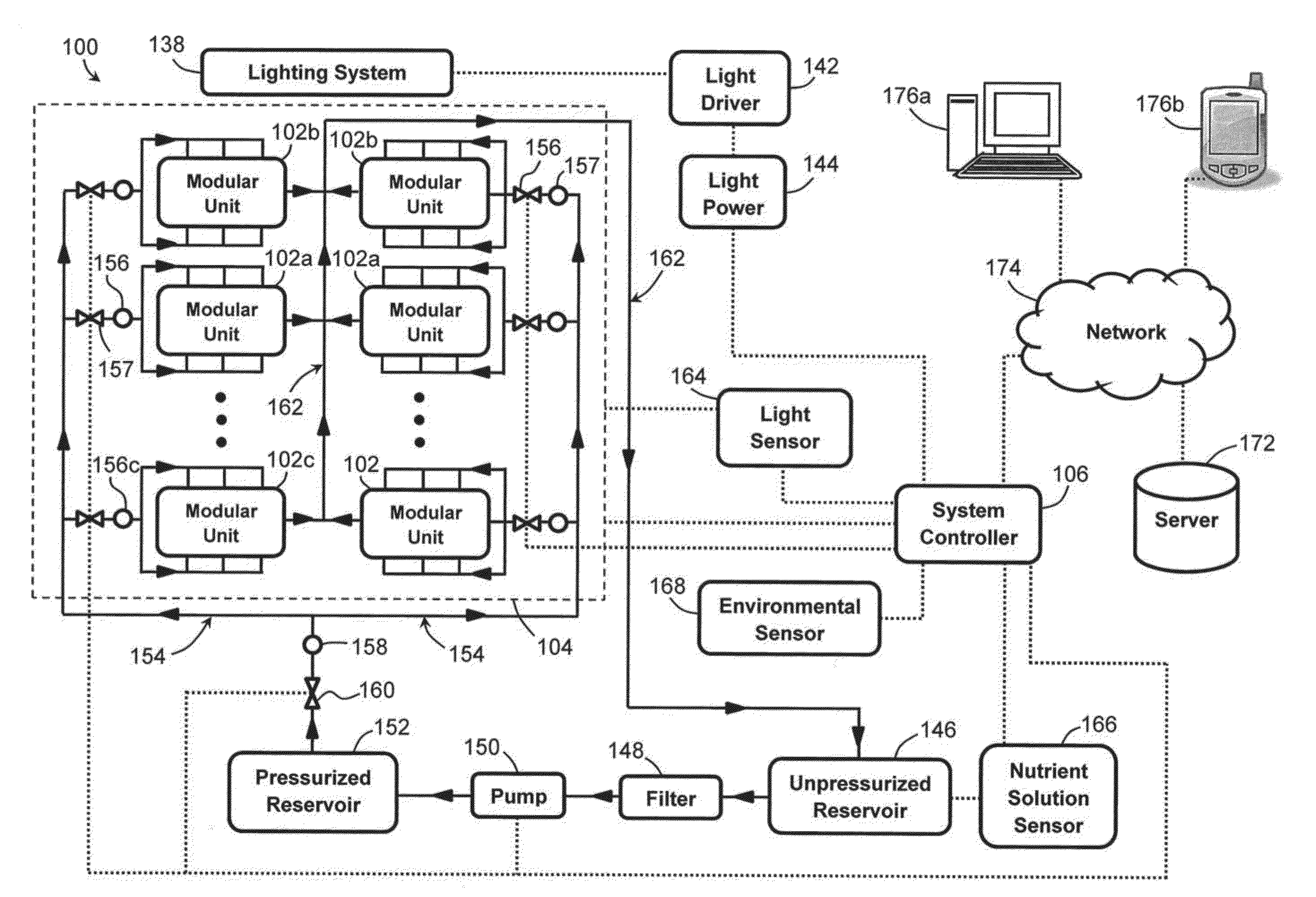
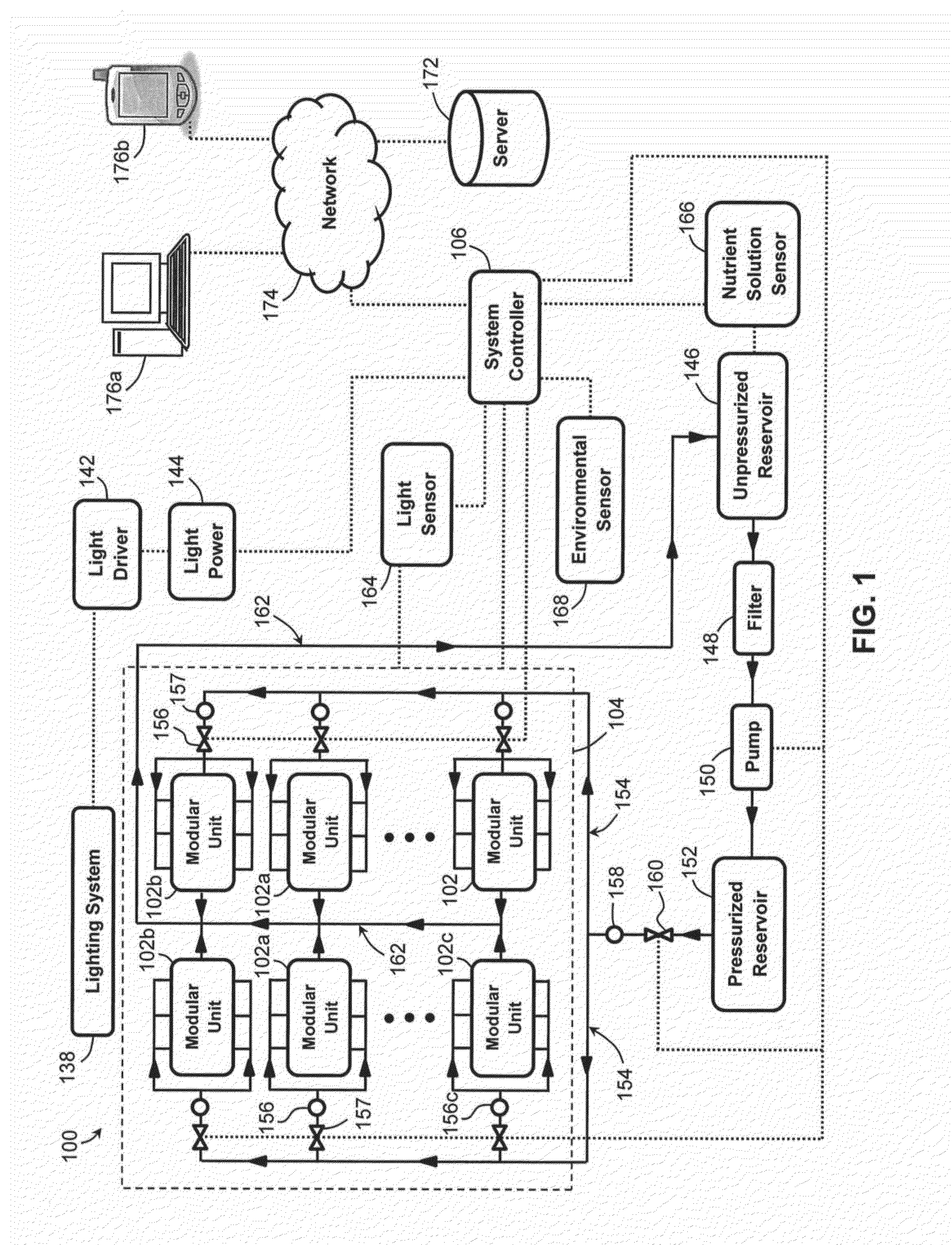
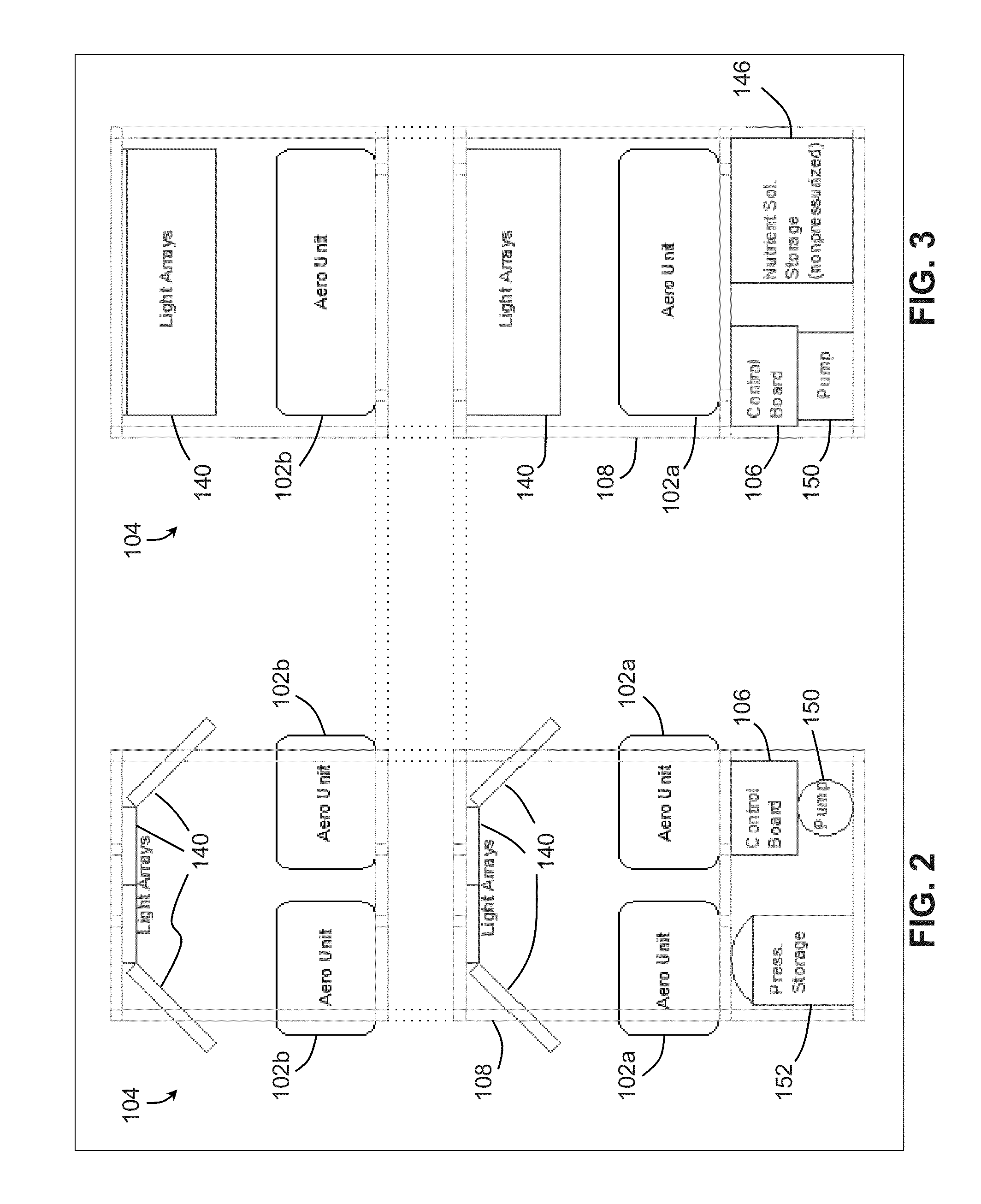
[0028]In general, the present invention provides a modular “plug-and-play” aeroponic growth system which allows for efficient maintenance and / or expansion of individual modular aeroponic units within the system without interrupting or otherwise disturbing the operation of other individual modular aeroponic units. The present system also configures the positioning and cone angles of the atomizers / misters (referred to herein as “spray nozzles”) and the structure of the modular aeroponic units to minimize the occurrence of wet or dry zones within a root zone. The present system also provides an automated system controller that may implement preprogrammed spray operations, monitor and control the temperature, humidity (i.e., activation of the spray nozzles), CO2 levels, light quality, light intensity, and other suitable plant growth parameters, and initiate alarms in the event of high or low sensor readings, pump failure, pressure loss, water loss, power failure or the occurrence of any...


PUM


Abstract

An aeroponic growth system comprising a plurality of modular aeroponic units each including at least one spray nozzle directed into a root zone; a lighting system associated with the plurality of the modular units and configured for emitting light in a vegetative zone; a pressurized reservoir configured for housing a nutrient containing fluid; and a nutrient feeding system configured for fluidly and selectively connecting each of the modular units to the pressurized reservoir in parallel, wherein the nutrient feeding system includes a pressure stop valve associated with each of the modular units. When one of the modular units are disconnected to the associated pressure stop valve, the pressure stop valve is configured for preventing the fluid from flowing from the pressurized reservoir through the pressure stop valve, and the other modular units connected to the nutrient feeding system remain fluidly connected to the pressure reservoir.

Description

CROSS-REFERENCE TO RELATED APPLICATIONS[0001]This application claims the benefit of U.S. Patent Application No. 61 / 729,754, filed Nov. 26, 2012, which is hereby incorporated by reference in its entirety.STATEMENT REGARDING FEDERALLY SPONSORED RESEARCH OR DEVELOPMENT[0002]This invention was made with government support under Contract Number SU-8347570 awarded by the Environmental Protection Agency. The government has certain rights in the invention.FIELD OF THE INVENTION[0003]The present patent application is directed to a modular automated aeroponic growth system for growing different types of plants; in particular the system includes a plurality of modular aeroponic units that are fluidly connected to a pressurized nutrient source in parallel and configured to be easily removed and added to provide a scalable plug and play growth system. The system may also utilize certain nozzle spacing, spray direction and cone angles to reduce variation in the growth of plants by minimizing dry ...

Claims


Application Information

Patent Timeline
Patent Type & Authority Applications(United States)
IPC IPC(8): A01G31/02
CPCA01G31/02Y02P60/21
Inventor GONYER, DAEGANJONES, SHAUN
Owner GONYER DAEGAN
Why Eureka
Try Eureka