
Locking assembly and operation machine

A component and locking technology, applied in the direction of pivot connection, etc., can solve problems such as difficulty in plug insertion, achieve the effect of weakening positioning accuracy requirements and improving positioning and installation speed

Active Publication Date: 2022-05-31
SANY AUTOMOBILE HOISTING MACHINERY
View PDF16 Cites 0 Cited by
  • Summary
  • Abstract
  • Description
  • Claims
  • Application Information

AI Technical Summary

Problems solved by technology

[0005] The present invention provides a locking assembly and a working machine, which is used to solve the defect in the prior art that it is difficult to insert the bolt due to the inability to adjust the displacement mechanism, and realize the swing body Precise positioning, flexible locking of locking structure, and adjustable position

Method used


Image

  • Locking assembly and operation machine
  • Locking assembly and operation machine
  • Locking assembly and operation machine

Examples


Embodiment Construction

[0032] In order to make the objectives, technical solutions and advantages of the present invention clearer, the technical solutions in the present invention will be clearly and completely described below with reference to the accompanying drawings. Obviously, the described embodiments are part of the embodiments of the present invention. , not all examples. Based on the embodiments of the present invention, all other embodiments obtained by those of ordinary skill in the art without creative efforts shall fall within the protection scope of the present invention.

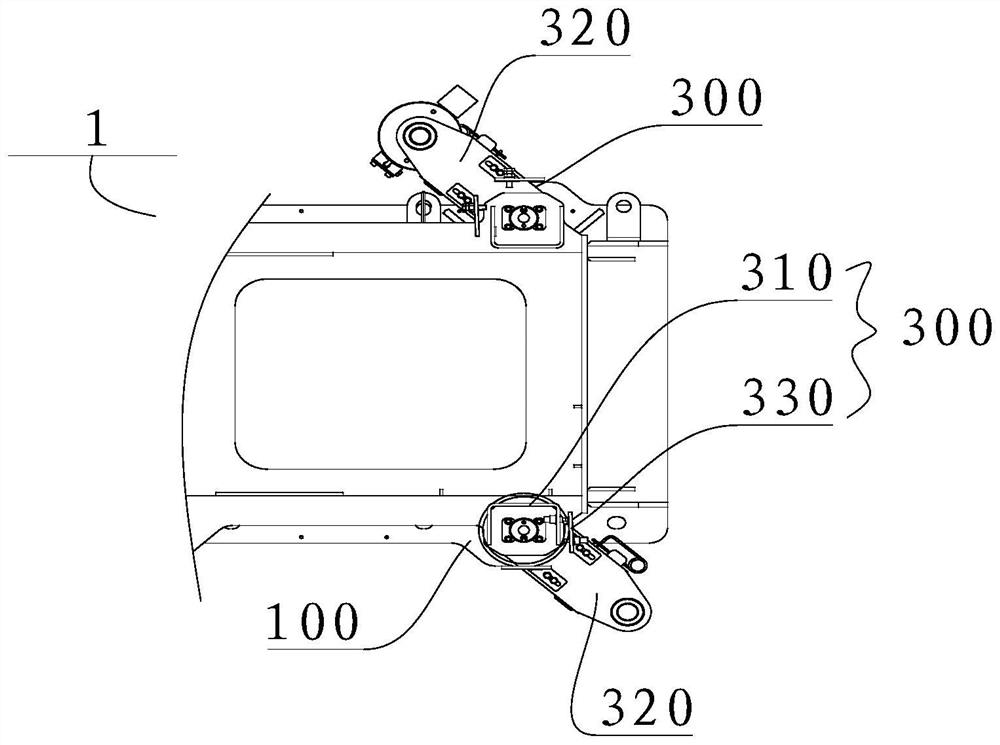
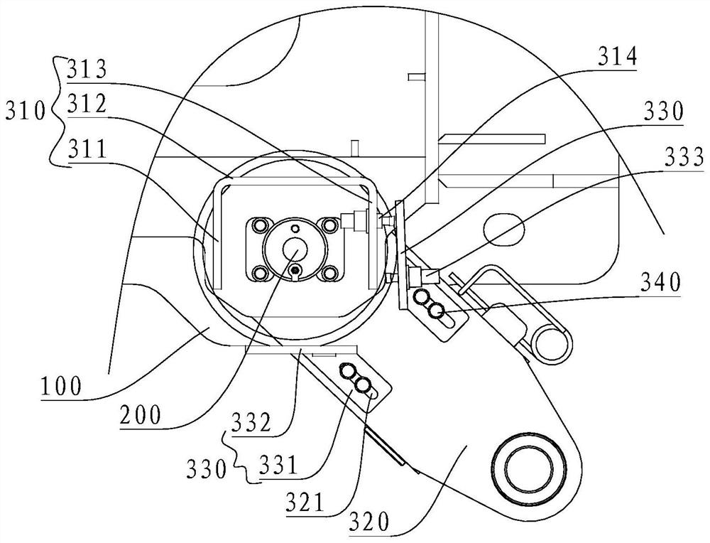
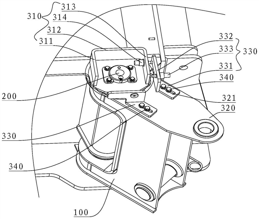
[0033] Combine below Figure 1 to Figure 6 The locking assembly 300 and work machine 1 of the present invention are described. In addition, the working machine 1 may be a crane.

[0034] combine figure 1 and figure 2 As shown, the work machine 1 according to the embodiment of the present invention includes a hoisting box 100 , a locking assembly 300 and a rotating shaft 200 .

[0035] The locking assembly 300...


PUM


Abstract

The invention relates to the technical field of engineering machinery, in particular to a locking assembly and an operation machine. The locking assembly comprises a first locking part, a second locking part and a swing body, a first telescopic part is arranged on the first locking part, the swing body is suitable for rotating around the first locking part among a plurality of preset positions, a second telescopic part is arranged on the second locking part, and when the swing body is located at at least one of the preset positions, the first telescopic part can rotate around the second telescopic part. A part of the structure of the first telescopic part extends out to abut against the second locking part, and a part of the structure of the second telescopic part extends out to abut against the first locking part, so that the first locking part and the second locking part are locked. According to the locking assembly provided by the invention, the first locking part and the second locking part can be locked at the preset position by utilizing the telescopic function of the first telescopic part and the second telescopic part, so that the requirement on the positioning precision of the first locking part and the second locking part is weakened, and the positioning and mounting speed of the first locking part and the second locking part can be further increased.

Description

technical field [0001] The invention relates to the technical field of construction machinery, in particular to a locking assembly and a working machine. Background technique [0002] Crane refers to a multi-action hoisting machine that vertically lifts and horizontally transports heavy objects within a certain range. Cranes include tire cranes and overhead cranes. Some of the working characteristics of lifting equipment are intermittent movement, that is, the corresponding mechanisms for taking materials, transporting, unloading and other actions in a working cycle work alternately. The development and use of cranes in the market are becoming more and more extensive. Due to the fact that some accidents often occur without outrigger lifting and hoisting, the driving speed is also faster than that of crawler cranes; the operation is stable, the lifting capacity is large, and it can be hoisted within a specific range, but it must be ensured that the road is flat and solid, an...

Claims


Application Information

Patent Timeline
Patent Type & Authority Applications(China)
IPC IPC(8): F16C11/04F16C11/10
CPCF16C11/04F16C11/10
Inventor 杨娟喻露荆凯
Owner SANY AUTOMOBILE HOISTING MACHINERY
Learn More