Eureka AIR delivers breakthrough ideas for toughest innovation challenges, trusted by R&D personnel around the world.

Installation method of tire crane saddle beam jacking support flange plate

A support flange plate and installation method technology, applied in the direction of auxiliary devices, auxiliary welding equipment, welding equipment, etc., can solve the problems of flange plate edge misalignment, flange bonding surface gaps, etc., to reduce surface deformation, The effect of ensuring assembly accuracy and assembly efficiency

Active Publication Date: 2021-04-06
SHANGHAI ZHENHUA HEAVY IND
View PDF6 Cites 0 Cited by
  • Summary
  • Abstract
  • Description
  • Claims
  • Application Information

AI Technical Summary

Problems solved by technology

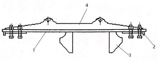
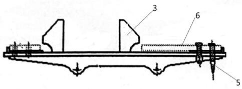
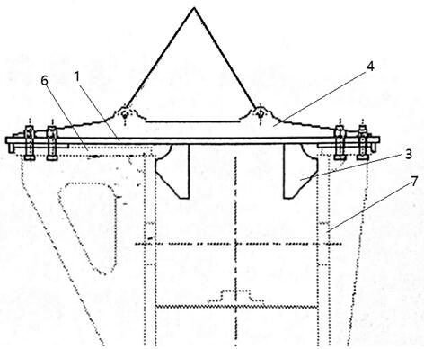
[0004] The technical problem to be solved by the present invention is to provide a method for installing the flange plate of the saddle beam jacking support of the tire crane, which can solve the problem of dislocation of the bolt holes and edge misalignment of the flange plate in the assembly of the flange plate of the saddle beam jacking support of the general tire crane. gap problem

Method used


Image

  • Installation method of tire crane saddle beam jacking support flange plate
  • Installation method of tire crane saddle beam jacking support flange plate
  • Installation method of tire crane saddle beam jacking support flange plate

Examples


Embodiment Construction

[0023] In order to make the purpose, technical solutions and advantages of the embodiments of the present invention clearer, the technical solutions in the embodiments of the present invention will be clearly and completely described below in conjunction with the drawings in the embodiments of the present invention. Obviously, the described embodiments It is a part of embodiments of the present invention, but not all embodiments. The components of the embodiments of the invention generally described and illustrated in the figures herein may be arranged and designed in a variety of different configurations.

[0024] Accordingly, the following detailed description of the embodiments of the invention provided in the accompanying drawings is not intended to limit the scope of the claimed invention, but merely represents selected embodiments of the invention. Based on the embodiments of the present invention, all other embodiments obtained by persons of ordinary skill in the art wi...


PUM


Abstract

The invention relates to an installation method of a tire crane saddle beam jacking support flange plate. The installation method is characterized by specifically comprising the following steps that S1, a flange plate installation plate is measured and scribed; S2, a tool is manufactured; S3, the tool is turned over; S4, a flange plate is locked and positioned; S5, the flange plate installation plate and the flange plate are turned over and hoisted; S6, the flange plate is welded;S7, the tool is disassembled; a flange preassembling area is arranged on a flange plate positioning plate, initial relative position positioning of a flange is guaranteed, and when the flange plate is preassembled on the tool, a guide pin is used for positioning the flange plate, and then the flange plate is fixed through a process bolt; when the tool and the flange plate are hoisted to a saddle beam jacking support, a guide plate is embedded into the end of a saddle beam, the positioning and mounting speed is increased while the butt joint quality of the flange plate is guaranteed, meanwhile, surface deformation, caused by welding, of the flange plate is reduced, and after the flange plate is welded, the process bolt connected with the tool is dismounted to be hoisted away from the tool. The mounting method of the flange plate ensures the assembly precision and the assembly efficiency of the flange plate.

Description

technical field [0001] The invention relates to the technical field of installation of a flange plate on a saddle beam jacking support, in particular to a method for installing a flange plate on a saddle beam jacking support of a tire crane. Background technique [0002] Rubber-tyred container gantry cranes (referred to as tire cranes) are widely favored by container yard users because of their flexible transfer capabilities. The traveling mechanism of the cart with 90-degree steering function. In order to reduce the tire wear during the steering process of the tire crane, a lifting device is arranged under the saddle beam structure to lift the whole machine of the tire crane to lift the tire off the ground; [0003] The jacking device is installed on the lower part of the saddle beam through the connecting flange, and the corresponding support is designed on the steel structure of the saddle beam. The manufacturing and installation precision of this support is high. On the...

Claims


Application Information

Patent Timeline
Patent Type & Authority Applications(China)
IPC IPC(8): B23K31/02B23K37/047B23K37/00
CPCB23K31/02B23K37/047B23K37/00
Inventor 黄叶锋陈云新王绍东朱勇
Owner SHANGHAI ZHENHUA HEAVY IND
Why Eureka
Eureka Blog
Learn More