Quick aligning device for wood splicing

A wood and fast technology, which is applied in the direction of wood processing appliances, wooden veneer joints, manufacturing tools, etc., can solve the problem of unusable wood and achieve the effect of reducing the time required for wood splicing

Active Publication Date: 2022-06-03
贵州群山木业有限公司
View PDF6 Cites 4 Cited by
  • Summary
  • Abstract
  • Description
  • Claims
  • Application Information

AI Technical Summary

Problems solved by technology

[0005] In order to overcome the disadvantage that the existing quick alignment device for wood splicing does not limit the wood, it is difficult for the staff to ensure that the wood is placed in the corresponding position when placing the wood, which will make the spliced ​​wood unusable. Provide A quick alignment device for wood splicing that can limit the position of the wood so that the wood is aligned and placed in the correct position for splicing

Method used


Image

  • Quick aligning device for wood splicing
  • Quick aligning device for wood splicing
  • Quick aligning device for wood splicing

Examples


Embodiment 1

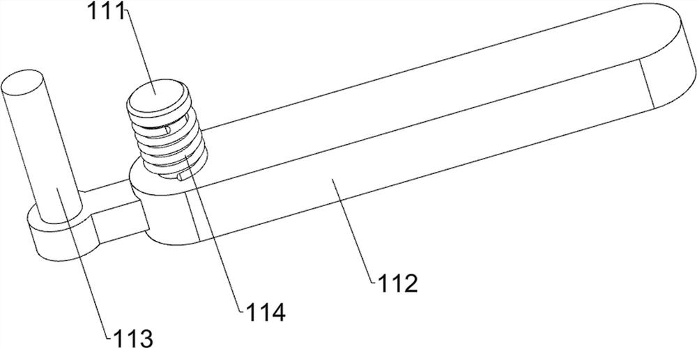
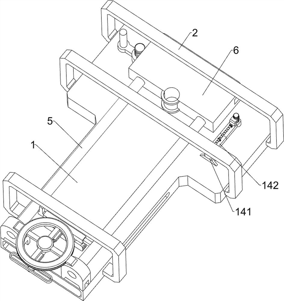
A quick alignment device for wood splicing, refer to Figure 1-Figure 3 As shown, it includes a base plate 1, a first mounting frame 2, a mounting block 3, a second mounting frame 4, a mounting rod 5, a positioning plate 6, a driving wheel 71, a first sliding sleeve 72, a driving rod 73, a guide rod 74, The first push plate 75 , the first compression spring 76 , the alignment mechanism 11 , the limit mechanism 12 , the guide mechanism 13 and the correction mechanism 14 . A mounting block 3 is welded, a second mounting frame 4 is welded on the left side of the bottom plate 1, a mounting rod 5 is welded on the mounting block 3, and a positioning plate 6 is fixed between the right ends of the mounting rod 5, and the positioning plate 6 can place the wood. The upper side of the mounting block 3 is rotatably connected with a driving wheel 71, the left side of the positioning plate 6 is provided with positioning holes symmetrically up and down, and the left side of the front mounting...

Embodiment 2

On the basis of Example 1, refer to figure 1 , Figure 12 and Figure 13 As shown, it also includes a fixing mechanism 15, which can place the connector. The fixing mechanism 15 includes a mounting sleeve 151, a blanking frame 152, a fourth compression spring 153, a second push plate 154, a connecting plate 155, The second guide rod 156 , the fifth compression spring 157 and the baffle plate 158 are all welded with a mounting sleeve 151 in the middle of the mounting rod 5 , and a blanking frame 152 is welded between the mounting sleeves 151 , and the blanking frame 152 can place the connecting device. A second push plate 154 is slidably arranged on the right side of the blanking frame 152, a fourth compression spring 153 is connected between the left side of the second push plate 154 and the left side of the blanking frame 152, and a fourth compression spring 153 is welded on the right side of the blanking frame 152. The connecting plate 155, the right side of the connecting ...


PUM


Abstract

The invention relates to a wood aligning device, in particular to a rapid aligning device for wood splicing. According to the rapid alignment device for wood splicing, wood can be limited, and the wood can be spliced when the wood is aligned and placed at the correct position. According to the technical scheme, the rapid alignment device for wood splicing comprises a bottom plate, first mounting frames, mounting blocks, second mounting frames, mounting rods, a positioning plate and the like, the first mounting frames are arranged on the right side of the bottom plate in a bilateral symmetry mode, the mounting blocks are arranged on the left side of the top of the bottom plate in a front-back symmetry mode, and the second mounting frames are arranged on the left side of the bottom plate; mounting rods are arranged on the mounting blocks, and a positioning plate capable of positioning the placement position of wood is connected between the right ends of the mounting rods. And the wood on the left side can be limited to the maximum moving position through the aligning rod, the wood on the right side can be limited through the limiting plate, in this way, automatic alignment can be achieved when the wood is conveyed, the position cannot deviate, and therefore splicing work can be conveniently carried out.

Description

technical field [0001] The invention relates to a wood aligning device, in particular to a quick aligning device for wood splicing. Background technique [0002] In the process of using wood, sometimes two pieces of wood need to be spliced ​​together for use. When the wood is spliced, it is necessary to align the wood first and then splicing, and the auxiliary device can be used at this time. [0003] The existing quick alignment device for wood splicing includes a base plate, a first mounting frame, a mounting block, a second mounting frame, a mounting rod, a positioning plate, a driving wheel, a first sliding sleeve, a driving rod, a guide rod, a first push rod The plate and the first compression spring, the right side of the bottom plate is provided with a first mounting bracket symmetrically from left to right, the top left side of the bottom plate is provided with a mounting block symmetrically front and rear, the left side of the bottom plate is provided with a second ...

Claims


Application Information

Patent Timeline
Patent Type & Authority Applications(China)
IPC IPC(8): B27D1/10
CPCB27D1/10
Inventor 何耀武
Owner 贵州群山木业有限公司
Why Eureka
Try Eureka