Eureka AIR delivers breakthrough ideas for toughest innovation challenges, trusted by R&D personnel around the world.

Pipeline pipe gallery laying system based on urban information model

An urban information and model technology, applied in vertical pipelines, infrastructure engineering, buildings, etc., can solve problems such as inability to stand cranes, inability to hoist inter-layer pipelines, and inability to hoist cranes, etc., so as to facilitate the insertion into the elastic frame. , The installation of nails is convenient and quick, and the effect of avoiding adverse effects

Inactive Publication Date: 2022-06-03
郭柯成
View PDF0 Cites 0 Cited by
  • Summary
  • Abstract
  • Description
  • Claims
  • Application Information

AI Technical Summary

Problems solved by technology

During the construction of the interlayer pipeline in the pipe gallery, due to the height limit of the crane's boom and hook, the hoisting of the interlayer pipeline cannot be carried out, and the trestle bridge cannot stand on the crane due to the narrow site, nor can the crane be used for hoisting of the pipeline
[0003] In the prior art, when the pipeline laying system based on the urban information model is erected, the construction needs to occupy the road for a long time, causing huge interference to the urban traffic, and the dust and noise during the construction period will have a certain impact on the urban environment, so We propose a pipeline laying system based on urban information model

Method used


Image

  • Pipeline pipe gallery laying system based on urban information model
  • Pipeline pipe gallery laying system based on urban information model
  • Pipeline pipe gallery laying system based on urban information model

Examples


Embodiment Construction

[0026] The following will be combined with the accompanying drawings in the embodiments of the present invention, the technical solution in the embodiments of the present invention will be described clearly and completely, it is clear that the embodiments described are only a part of the embodiment of the present invention, not all embodiments.

[0027] Examples of the embodiments are shown in the accompanying drawings, wherein the same or similar labels from beginning to end represent the same or similar elements or elements with the same or similar functions. The embodiments described below by reference to the accompanying drawings are exemplary and are intended to be used to explain the present invention, and cannot be construed as a limitation of the present invention.

[0028] In the description of the present invention, it is to be understood that the terms "center", "longitudinal", "transverse", "length", "width", "thickness", "up", "down", "front", "back", "left", "right",...


PUM


Abstract

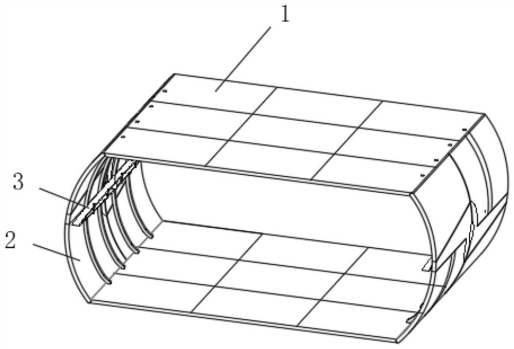
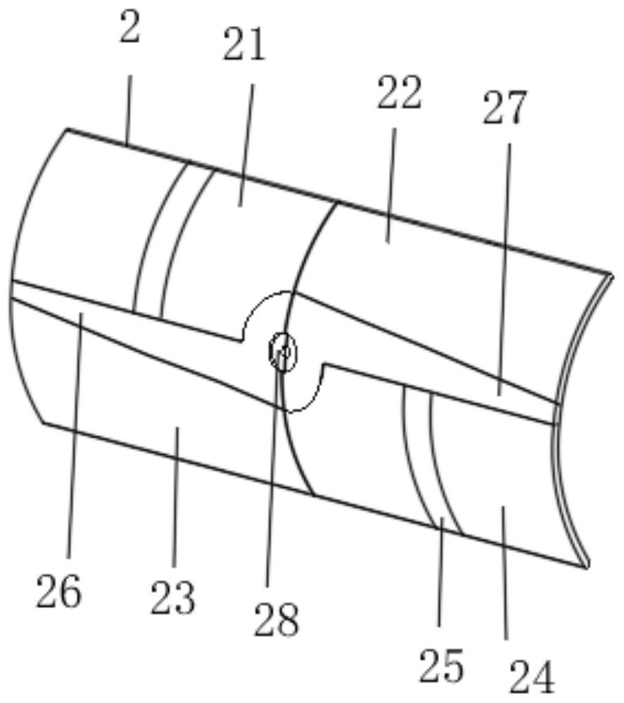
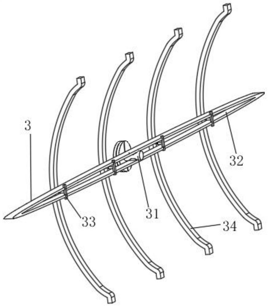
The invention relates to the technical field of pipeline pipe gallery laying, and discloses a pipeline pipe gallery laying system based on an urban information model, which comprises two underframes, clamping mechanisms are arranged at the ends, close to each other, of the two underframes, fixing devices are arranged on the surfaces of the clamping mechanisms, the number of the clamping mechanisms is two, and the number of the fixing devices is two. The two sets of clamping mechanisms and the fixing devices are symmetrically arranged with the center axis of the bottom frame as the center, after a second clamping plate and a third clamping plate are arranged, the first mounting frame, the second mounting frame, the third mounting frame and the fourth mounting frame can be spliced through the first clamping plate, a large amount of time is not needed for pouring construction and other operations, time is saved, and the working efficiency is improved. And by inserting a limiting plate and a connecting column, the limiting plate is clamped and fixed with the elastic frame through the connecting column, so that subsequent mounting and nailing of the mounting frame I, the mounting frame II, the mounting frame III and the mounting frame IV can be more convenient and rapid.

Description

Technical field [0001] The present invention relates to the technical field of pipeline pipe gallery laying, specifically a pipeline pipe gallery laying system based on the urban information model. Background [0002] Pipe corridors, that is, corridors of pipes. Many pipes in chemical and related plants are clustered together, arranged along the outside of the plant or plant, usually in the air, propped up with brackets, forming a similar appearance to corridors. There are also a few pipe galleries located underground. In the overhaul and transformation of chemical plants, it is often encountered to increase or decrease the pipeline of pipe corridors. In the use of pipe corridors, multi-layer arrangement is generally adopted, and the addition and replacement of inter-layer pipelines in pipe corridors has always been a problem in the installation of process pipelines. During the construction of the pipeline between the pipe corridors, due to the height restrictions of the crane's ...

Claims


Application Information

Patent Timeline
IPC IPC(8): E02D29/045E04F17/08
CPCE02D29/10E04F17/08E02D2600/20
Inventor 郭柯成
Owner 郭柯成
Why Eureka
Eureka Blog
Learn More